
A program-controlled power signal source output voltage multiplier circuit

A technology of power signal and output voltage, applied in the field of program-controlled power signal source output voltage multiplier circuit, can solve problems such as unworkability, and achieve the effect of fast response speed, good effect, and improved output amplitude

Active Publication Date: 2020-09-15
SHANGHAI WISCOM SUNEST ELECTRIC POWER TECH
View PDF5 Cites 0 Cited by
  • Summary
  • Abstract
  • Description
  • Claims
  • Application Information

AI Technical Summary

Problems solved by technology

[0008] In the above-mentioned first change, the 1000V withstand voltage PMOS is currently searched by various manufacturers, but cannot be found. This solution is temporarily unfeasible.

Method used


Image

  • A program-controlled power signal source output voltage multiplier circuit
  • A program-controlled power signal source output voltage multiplier circuit
  • A program-controlled power signal source output voltage multiplier circuit

Examples


Embodiment Construction

[0022] In order to make the object, technical solution and advantages of the present invention clearer, various embodiments of the present invention will be described in detail below in conjunction with the accompanying drawings.

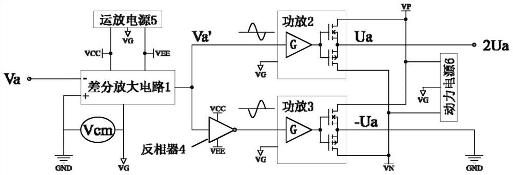
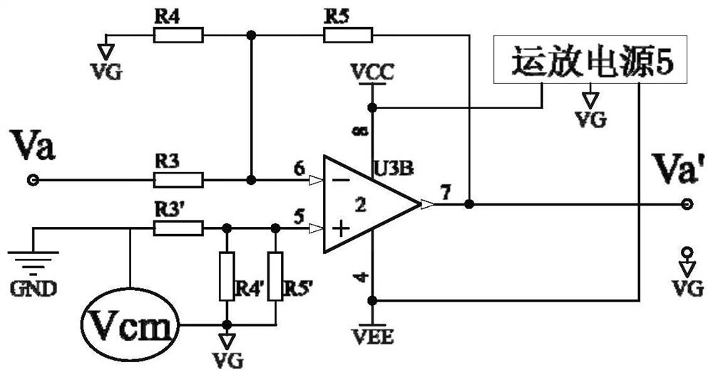
[0023] Such as figure 2 As shown, a programmable power signal source output voltage multiplication circuit includes a differential amplifier circuit 1, an operational amplifier power supply 5, a second power amplifier 2, a third power amplifier 3, an inverter 4 and a power supply 6, and the differential amplifier circuit 1 The input is connected to Va and the power amplifier system reference ground GND, the output is connected to the second power amplifier 2 and inverter 4, the output of the second power amplifier 2 is Ua, the output of inverter 4 is connected to the third power amplifier 3, and the output of the third power amplifier 3- Ua, the power supply 6 are respectively connected to the second power amplifier 2 and the third power amplifier ...


PUM


Abstract

The invention discloses an output voltage multiplier circuit for a programmable power signal source, comprising a differential amplifier circuit, an op amp power supply, a second power amplifier, a third power amplifier, an inverter, and a power supply. The differential amplifier circuit is connected to Va and the power amplifier system reference point GND, and the output is connected to the second power amplifier and the inverter. The second power amplifier outputs the Ua. The inverter output is connected to the third power amplifier. The third power amplifier outputs the -Ua. The power source is respectively connected to the second power amplifier and the third power amplifier. The op amp power supply is respectively connected to the differential amplifier circuit and the inverter. The -Ua is connected to the GND. The output voltage multiplier circuit for the programmable power signal source doubles the amplitude of the voltage output of the existing program-controlled power signal source, and has an excellent response speed and a high waveform playback effect.

Description

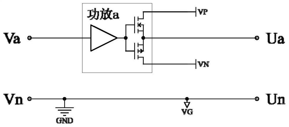
technical field [0001] The invention relates to the field of power distribution automation terminal testing, in particular to a program-controlled power signal source output voltage multiplication circuit. Background technique [0002] In the production, debugging and on-site testing of distribution automation terminals, the programmable power signal source is required to generate controllable voltage and current signals, which are input to the distribution automation terminals to determine whether their functions and performance are normal. [0003] The output voltage of the existing program-controlled power signal source can only reach AC 120V. For some distribution automation terminals working on the AC 220V system, especially the distribution automation terminals working on the AC 220V system that integrate supply and acquisition, it cannot meet the test requirements. . [0004] Analyze the existing programmable power signal voltage output structure, such as figure 1 A...

Claims


Application Information

Patent Timeline
Patent Type & Authority Patents(China)
IPC IPC(8): G05F1/625
CPCG05F1/625
Inventor 吴攀范志杰凌万水
Owner SHANGHAI WISCOM SUNEST ELECTRIC POWER TECH
Learn More