
Gradually-changed slot antenna combination structure with broadband coupling inhibition function

A technology of restraining effect and combined structure, which is applied in the direction of antenna grounding switch structure connection, slot antenna, radiation element structure, etc., can solve the problems affecting the working performance of the antenna, the antenna cannot work, etc., and achieve the improvement of electromagnetic compatibility, simple production, The effect of improving isolation

Inactive Publication Date: 2019-02-15
BEIHANG UNIV
View PDF1 Cites 2 Cited by
  • Summary
  • Abstract
  • Description
  • Claims
  • Application Information

AI Technical Summary

Problems solved by technology

This combination of antennas has high requirements on the isolation between the antennas. If the coupling between the antennas is severe, it will affect the performance of the antennas, and in severe cases, the antennas will not work.

Method used


Image

  • Gradually-changed slot antenna combination structure with broadband coupling inhibition function
  • Gradually-changed slot antenna combination structure with broadband coupling inhibition function
  • Gradually-changed slot antenna combination structure with broadband coupling inhibition function

Examples


Embodiment 1

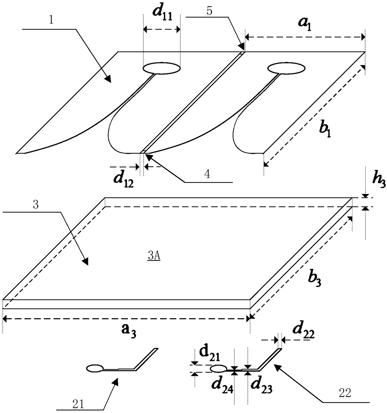
[0043] The working frequency band of the tapered slot antenna used in Embodiment 1 is 1-3 GHz, and the specific dimensions are as follows:

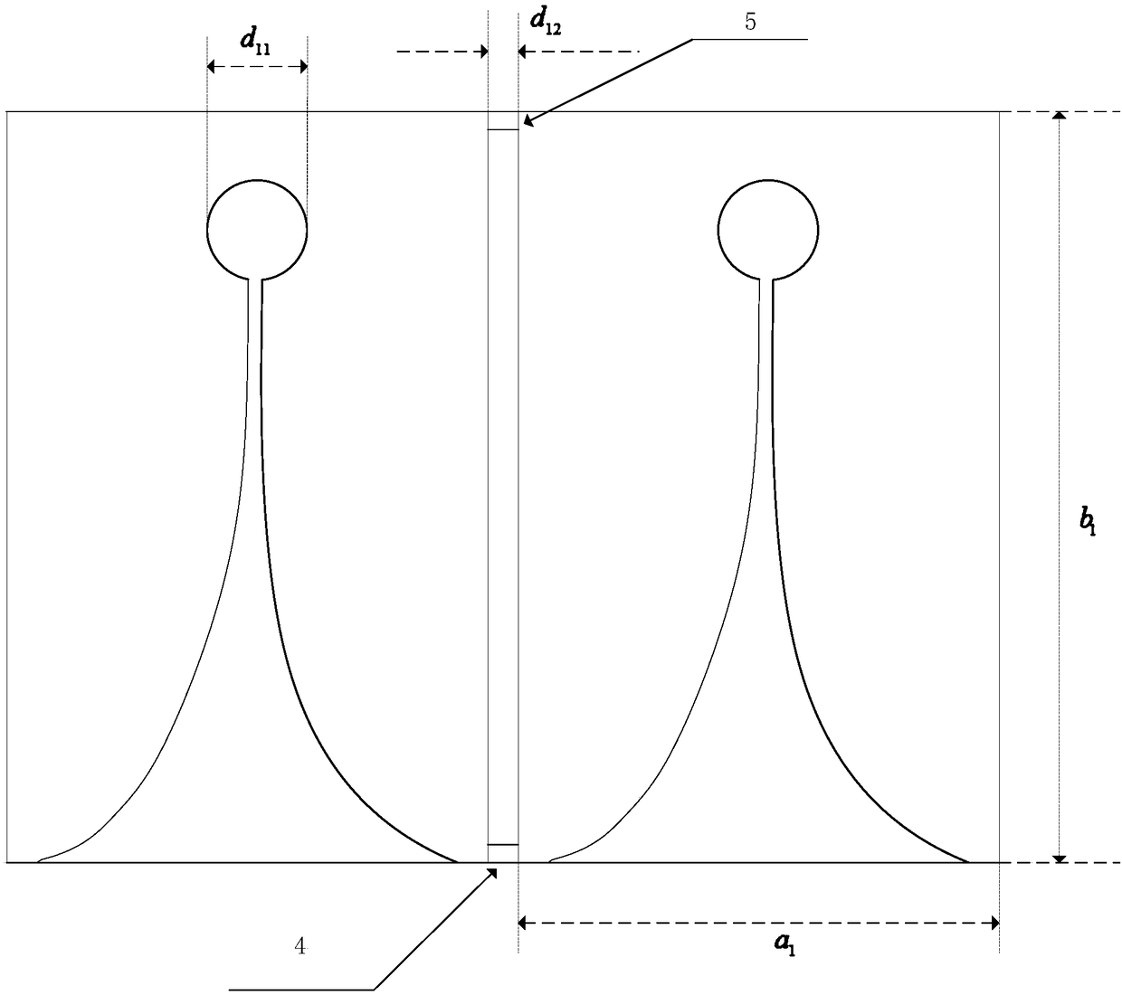
[0044] a 1 =139.5mm, a 3 =280mm,b 1 =b 3 =220mm;

[0045] d 11 =38mm;

[0046] d 12 = 1 mm;

[0047] h 3 =0.8mm;

[0048] d 21 = 16mm, d 22 = 2.2mm, d 23 = 2 mm, d 24 = 1 mm.

[0049] The performance evaluation of Embodiment 1 is performed by using S parameters: the dotted line in the figure represents the traditional antenna, and the solid line represents the designed antenna of Embodiment 1.

[0050] see Figure 2A As shown, the S11 parameter represents the working performance of the gradient slot antenna 1 , and its performance in the working frequency band of 1-2 GHz is basically unchanged before and after inductive loading.

[0051] see Figure 2B As shown, the S22 parameter represents the working performance of the gradient slot antenna 2, and its performance in the working frequency band of 1-2 GHz is basically uncha...


PUM


Abstract

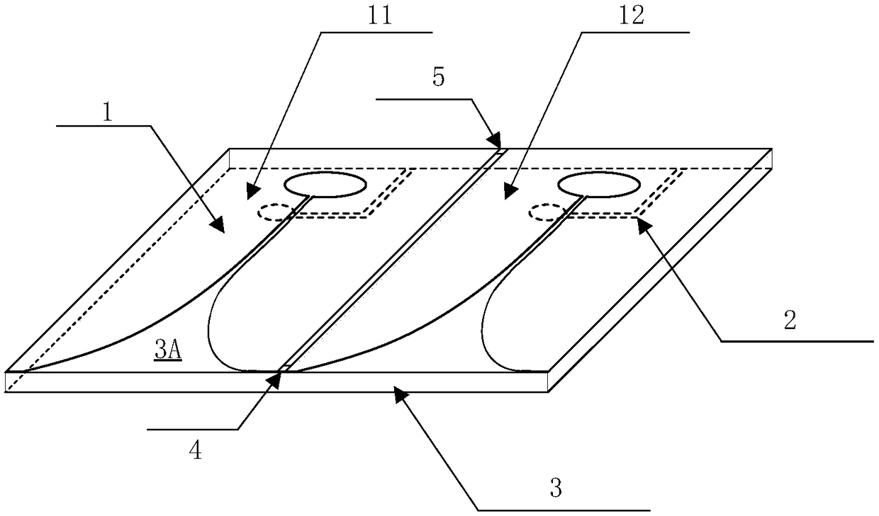
The invention relates to a gradually-changed slot antenna combination structure with a broadband coupling inhibition function. The gradually-changed slot antenna combination structure is composed of agradually-changed slot antenna unit and inductors; a gap is cut in the middle of the gradually-changed slot antenna unit, and the inductors are arranged at the two ends of the gap; the gradually-changed slot antenna unit is composed of an antenna working area patch unit, a dielectric plate and an antenna feed unit; the antenna working area patch unit consists of a first working area patch unit copper-clad configuration and a second working area patch unit copper-clad configuration for radiating electromagnetic waves; the first working area patch unit copper-clad configuration and the second working area patch unit copper-clad configuration are both manufactured on the front surface of the dielectric plate by adopting a copper-clad process; a circular open slot is formed in the antenna working area patch unit; the antenna feed unit is formed by a first feed unit copper-clad configuration and a second feed unit copper-clad configuration for feeding; and the first feed unit copper-clad configuration and the second feed unit copper-clad configuration are both manufactured on the back surface of the dielectric plate by adopting a copper-clad process.

Description

technical field [0001] The invention relates to an antenna combination, more particularly, to a tapered slotted antenna combination structure with broadband coupling suppression effect. The antenna combination involved in the present invention is suitable for systems such as airborne common-aperture antennas, and is an antenna combination with electromagnetic compatibility. Background technique [0002] The design and optimization of airborne antennas have recently received extensive attention. The design methods and principles of airborne antennas are different from those on other platforms. Airborne platforms have higher requirements for all aspects of antenna performance. Since the normal operation of the aircraft needs to obtain or send information such as communication, altitude, fuel level, landing, and weather at the same time, the number of antennas on the aircraft platform is large, which makes the aircraft platform have higher requirements for the isolation betwe...

Claims


Application Information

Patent Timeline
Patent Type & Authority Applications(China)
IPC IPC(8): H01Q1/38H01Q1/50H01Q13/10
CPCH01Q1/38H01Q1/50H01Q13/10
Inventor 马振鹏吴琦
Owner BEIHANG UNIV
Learn More