
Planet running impact type descent control device damping device

A technology of damping device and descending device, applied in life-saving equipment, building rescue and other directions, can solve the problems of high cost, reduced friction coefficient, large quality, etc., and achieve the effects of compact structure, corrosion prevention and low cost.

Active Publication Date: 2019-02-19
BEIHUA UNIV
View PDF9 Cites 12 Cited by
  • Summary
  • Abstract
  • Description
  • Claims
  • Application Information

AI Technical Summary

Problems solved by technology

The main problem of this kind of friction damping device is that it is afraid of water and oil, that is, once water, oil and other media enter the friction pair, the damping effect will be greatly reduced due to the sharp drop of the friction coefficient, and even the slow down effect will fail.
On the contrary, the impact deformation of the fixed part is not easy to compensate, and has a great influence on the damping effect
[0007] "A damping device for a slow descender with metal particle medium" (Patent No. ZL201310656418.3), basically there is no impact wear, but the gear set of the speed increasing mechanism and the reverse gear set are relatively complicated, with many parts and high cost, and a large number of them are used Steel balls are used as granular media, which are of high quality and high cost

Method used


Image

  • Planet running impact type descent control device damping device
  • Planet running impact type descent control device damping device
  • Planet running impact type descent control device damping device

Examples


Embodiment Construction

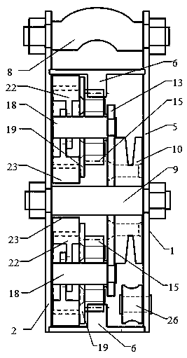
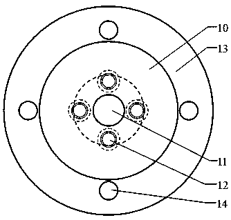
[0048] figure 1 It is a schematic diagram of the overall structure of a damping device (hereinafter referred to as the damping device) of a planetary-running impact-type descender provided by the present invention. The damping device includes a bottom cover 2, a buckle cover 5, an inner ring gear 6, a hanging shaft 8, a central shaft 9, a sheave 10, a pinion 15, a gear shaft 18, a chute 19, a centrifugal block 22, and a guide limit wheel 26. . The hanging shaft 8 is installed between the bottom cover 2 and the buckle cover 5 and is located at the top.

[0049] Such as Figure 15 , 16 , 2 and Figure 5 As shown, the bottom cover 2 is provided with a coaxial bottom cover central hole 3 and an annular groove 4, and the inner side of the buckle cover 5 also has the same structure. The two ends of the ring gear 6 are assembled with the annular groove 4 of the bottom cover 2 and the buckle cover 5 . One end of the central shaft 9 is assembled with the central hole 3 of the bo...


PUM


Abstract

The invention relates to the field of high-altitude rescue descend control devices, in particular to a planet running impact type descent control device damping device. A special impact damping manneris mainly adopted for achieving constant-speed slow descending, and the problem that the slow descending effect is influenced by impact wear is solved. In the structure, a fixed inner gear ring is arranged in a box body, four small gears are assembled on a rope sheave and engaged with the inner gear ring, the rope sheave drives the four small gears to do planet rotating running, each small gear drives a pair of centrifugal blocks to rotate at a high speed and do planet running through a sliding groove, and through centrifugal force, mutual impacting and friction happen between the centrifugalblocks in the different sliding grooves and between the centrifugal blocks and the inner wall of the box body. When the gear ratio of the gear ring and the gears is not an integer, the centrifugal blocks constantly move and change at the impact point of the inner wall of the box body. Due to the fact that impacting damping is adopted as the main and the damping effect cannot be influenced by wearof the centrifugal blocks and the inner wall of the box body, the device is waterproof and oil-proof and is stable in performance, long in service life, compact in structure, small in size and low inmanufacturing cost.

Description

technical field [0001] The invention relates to a high-altitude lifesaving slow-down device, in particular to a damping device for a planetary running impact type slow-down device. Background technique [0002] Most of the high-altitude lifesaving slow-descent devices in the prior art are mainly composed of three parts, namely a rope winding mechanism, a speed-increasing mechanism (gear set) and a damping device. Most of the damping devices are friction type, and the structure is mainly a friction pair composed of high-speed rotating parts (centrifugal body) and fixed parts (such as the inner circular surface of the box body). The centrifugal force of the high-speed rotating parts (centrifugal body) makes the friction pair Friction is generated between them, and the rotation speed of the rope winding mechanism is limited to achieve the purpose of slow down at a constant speed. The main problem of this kind of frictional damping device is that it is afraid of water and oil, ...

Claims


Application Information

Patent Timeline
Patent Type & Authority Applications(China)
IPC IPC(8): A62B1/10
CPCA62B1/10
Inventor 吕雪寒张志义叶延亮
Owner BEIHUA UNIV
Learn More