Three-dimensional space random-direction fusion-covering forming method

A technology of any direction and molding method, applied in the direction of process efficiency improvement, energy efficiency improvement, additive manufacturing, etc., can solve the problems of easy flow of molten pool, polluted mirror surface, damage of focusing mirror, etc., to ensure the effect of not being polluted

Inactive Publication Date: 2019-02-19
SUZHOU UNIV
View PDF9 Cites 1 Cited by
  • Summary
  • Abstract
  • Description
  • Claims
  • Application Information

AI Technical Summary

Problems solved by technology

[0003] In the laser cladding process, the cladding nozzle is generally required to be perpendicular to the processing base surface all the time. When the inclination angle of the base surface is larger, the inclination angle of the cladding nozzle is also larger, and the cladding nozzle ejected in the space The coupling effect between the cladding material and the focused beam will be worse, and the inclined high-temperature molten pool is more likely to flow or even drip. In addition, only a part of the cladding material injected synchronously enters the molten pool to be melted, and a part is rebounded by the surface of the molten pool. A part of the cladding material sprayed outside the molten pool is rebounded on the processing base surface. Generally, the larger the working inclination angle of the cladding nozzle, the easier it is for the rebounded and splashed cladding material to enter the inner cavity of the support frame under the cladding nozzle In particular, for cladding nozzles that perform cladding operations at large inclination angle processing positions and upward positions, the splashed cladding material will directly enter

Method used


Image

  • Three-dimensional space random-direction fusion-covering forming method
  • Three-dimensional space random-direction fusion-covering forming method
  • Three-dimensional space random-direction fusion-covering forming method

Examples


Embodiment Construction

[0028] The specific implementation manners of the present invention will be further described in detail below in conjunction with the accompanying drawings and embodiments. The following examples are used to illustrate the present invention, but are not intended to limit the scope of the present invention.

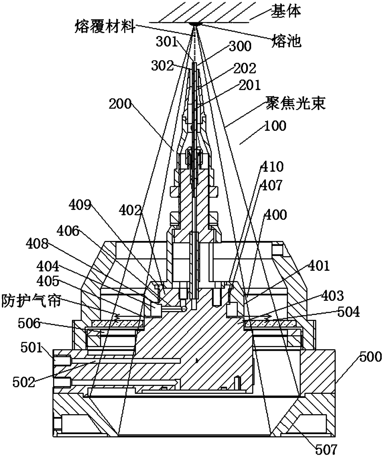
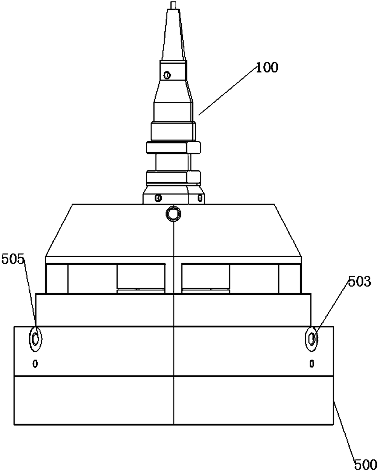
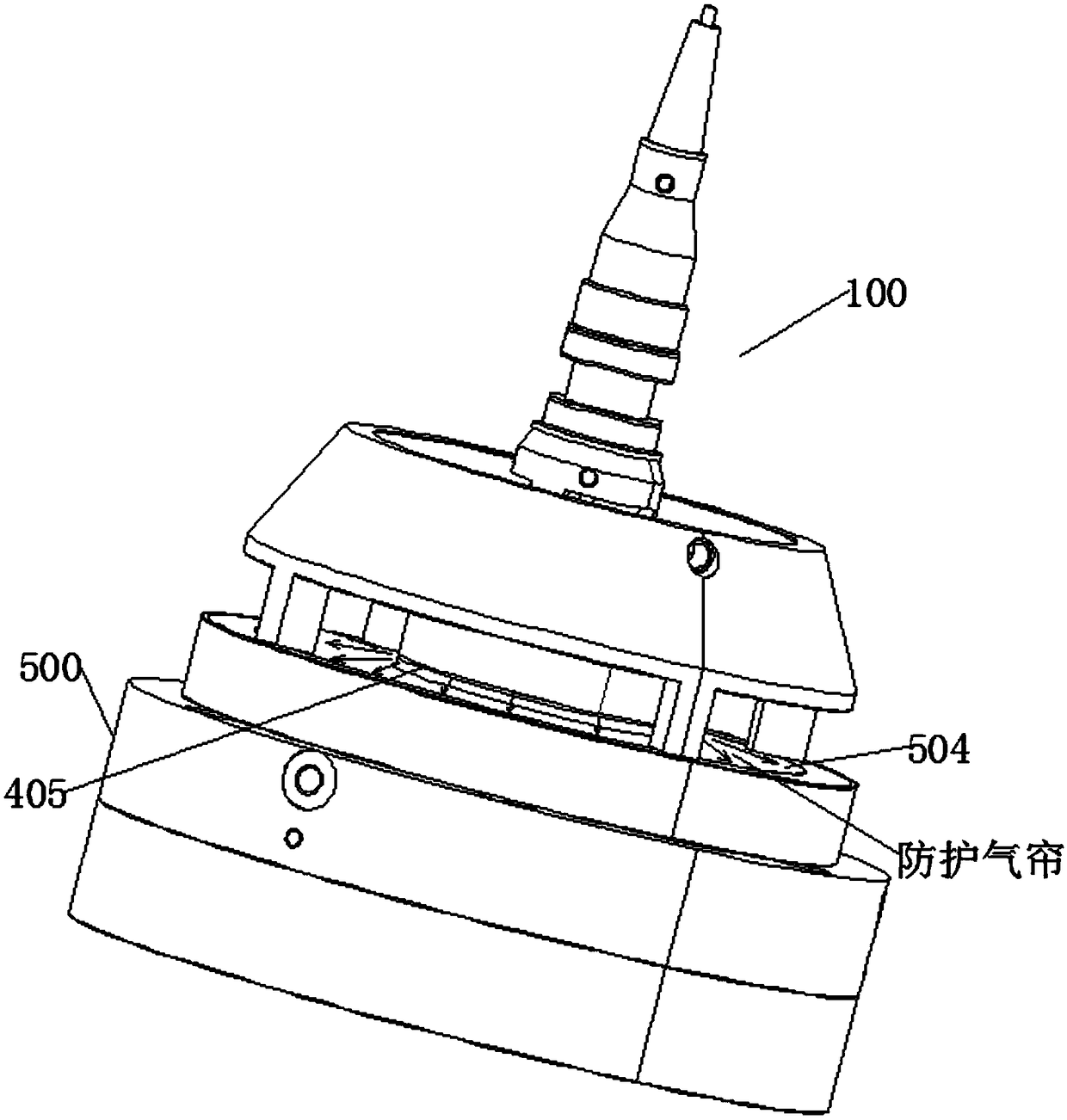
[0029] See Figure 1-3 , a cladding molding method in any direction in three-dimensional space according to Embodiment 1 of the present invention is mainly used to prevent the cladding material from splashing and adhering to the focusing mirror 507 when the laser cladding device continuously changes its orientation, so as to prevent the focusing mirror 507 from being damaged due to For the problem of damage caused by cladding materials, the cladding molding method in any direction in three-dimensional space includes the following steps: providing a substrate with a surface that needs cladding accumulation or cladding repair, and the cladding material passes through the cla...


PUM

PropertyMeasurementUnit
Granularityaaaaaaaaaa

Abstract

The invention relates to a three-dimensional space random-direction fusion-covering forming method. The three-dimensional space random-direction fusion-covering forming method comprises the followingsteps of: providing a base body which is provided with surface needing fusion-covering accumulation or being repaired by fusion-covering, spraying a fusion-covering material to the surface of the basebody from a spray nozzle through a fusion-covering channel of a spray head main body, and focusing laser to the surface of the base body through a focusing lens to fusion-cover the fusion-covering material onto the surface of the base body; and forming a protective gas curtain for blowing away/isolating the fusion-covering material, which is not fusion-covered between the focusing lens and the spray nozzle, between the spray nozzle and the focusing lens. According to the three-dimensional space random-direction fusion-covering forming method provided by the invention, when a laser fusion-covering device is in large-angle inclination and vertical face-up fusion-covering or space continuous direction change, fusion-covering material fed out from the spray nozzle does not splash down on thefocusing lens to damage the focusing lens, so that stability and reliability of fusion-covering are guaranteed, and +/-180-degree three-dimensional space all-around random-direction fusion-covering isrealized.

Description

technical field [0001] The invention relates to a cladding molding method in any direction in three-dimensional space, which belongs to the field of laser processing. Background technique [0002] Simultaneous-feed laser cladding is a major method for additive manufacturing of metal alloys. Laser cladding generally focuses the laser beam and projects it onto the processing base surface to form a working spot. At the same time, the cladding material is synchronously delivered to the working spot. With the scanning movement of the cladding nozzle, it is put into the work of moving on the processing base surface. The cladding material in the spot melts, solidifies and forms a continuous melt path. [0003] In the laser cladding process, the cladding nozzle is generally required to be perpendicular to the processing base surface all the time. When the inclination angle of the base surface is larger, the inclination angle of the cladding nozzle is also larger, and the cladding n...

Claims


Application Information

Patent Timeline
IPC IPC(8): B22F3/105B33Y10/00B33Y30/00B33Y70/00
CPCB33Y10/00B33Y30/00B33Y70/00B22F10/00B22F12/44B22F10/25B22F10/36B22F10/366B22F12/53B22F10/32Y02P10/25
Inventor 石拓石世宏蒋伟伟傅戈雁
Owner SUZHOU UNIV
Why Eureka
Try Eureka