
Lubricating equipment for chain teeth

A technology for lubricating equipment and sprockets, applied in mechanical equipment, belts/chains/gears, cleaning methods using liquids, etc., can solve the problems of difficult cleaning, reduced lubricating ability, wear of parts, etc., and achieve the effect of simple operation

Active Publication Date: 2018-08-24
TIANJIN JINYA ELECTRONICS
View PDF5 Cites 0 Cited by
  • Summary
  • Abstract
  • Description
  • Claims
  • Application Information

AI Technical Summary

Problems solved by technology

[0003] After the chain is used for a long time, the various parts in the chain will rub against each other, and the debris generated during the friction process will be integrated into the lubricating oil on the chain. After the lubricating oil adheres to the debris during this process, the lubricating ability is reduced. At the same time, the debris in the lubricating oil is easily located between the two rotating parts, which will increase the wear between the parts, so when the lubricating oil on the chain turns black or is extremely dry, it is necessary to clean the lubricating oil on the chain ; Common cleaning devices can only clean the two sides of the chain, and it is difficult to clean the rollers and sleeves between the chains comprehensively

Method used


Image

  • Lubricating equipment for chain teeth
  • Lubricating equipment for chain teeth

Examples


Embodiment Construction

[0017] Further detailed explanation through specific implementation mode below:

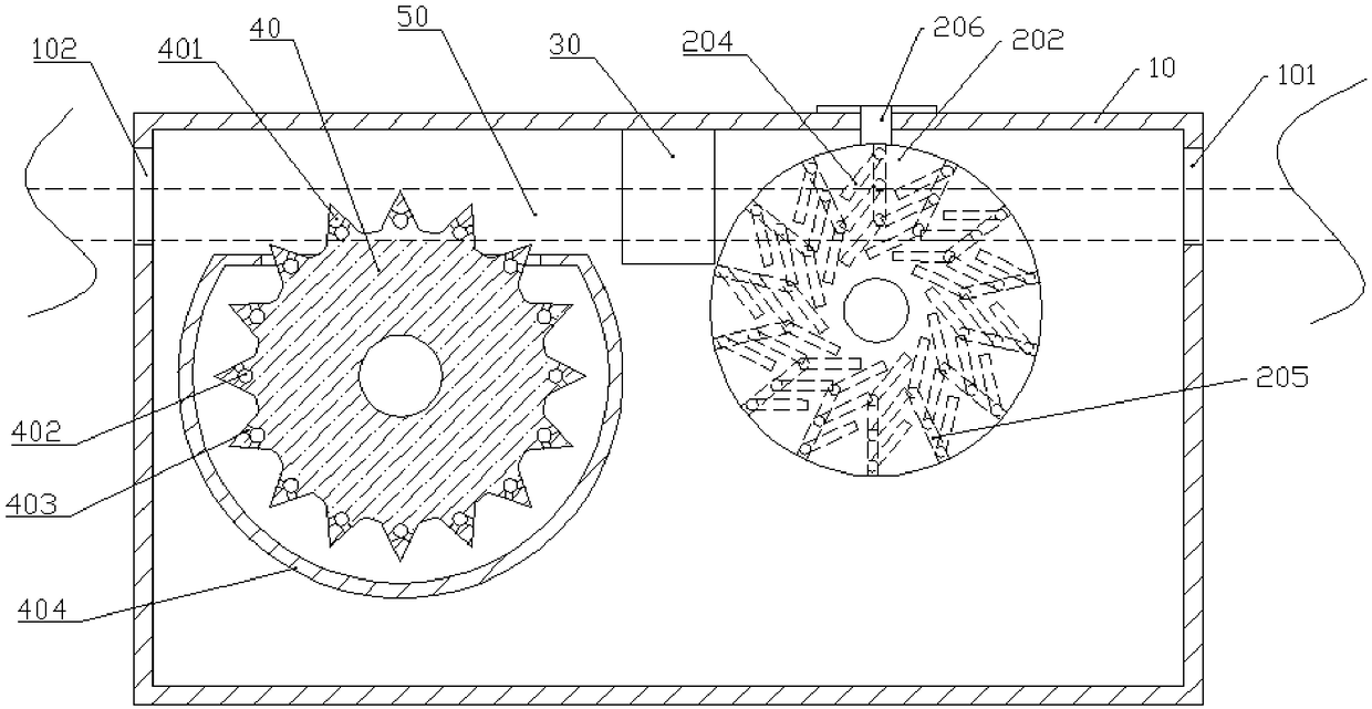
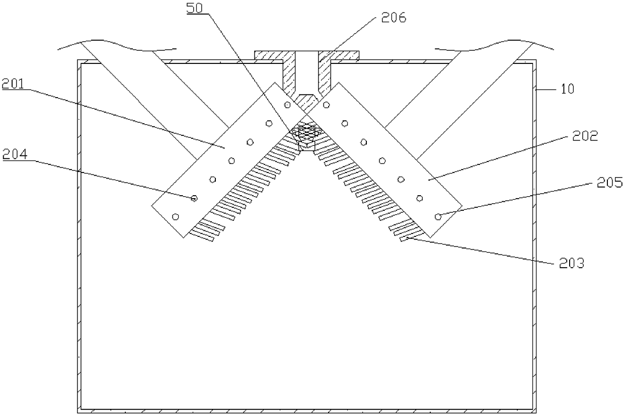
[0018] The reference signs in the accompanying drawings of the description include: casing 10, inlet 101, outlet 102, first cleaning tray 201, second cleaning tray 202, cleaning brush 203, first water inlet chamber 204, second water inlet chamber 205, Water inlet pipe 206, sponge 30, chain disc 40, sprocket 401, oil inlet pipe 402, oil outlet hole 403, inner shell 404, chain 50.

[0019] The embodiment is basically as attached figure 1 And attached figure 2 Shown: the lubricating equipment that is used for sprocket 401, comprises casing 10, drying unit and the cleaning mechanism and transmission mechanism that are arranged in casing 10, is provided with inlet 101 on the right side of casing 10, and the left side of casing 10 An outlet 102 is provided on the side. The cleaning mechanism is located on the right side of the cabinet 10, the transmission mechanism is located on the left side of th...


PUM


Abstract

The invention relates to the field of mechanical lubrication, and in particular, discloses lubricating equipment for chain teeth. The lubricating equipment comprises a cleaning mechanism and a conveying mechanism; the cleaning mechanism is positioned in an inlet of a shell; the conveying mechanism is positioned in an outlet of the shell; the cleaning mechanism comprises a first cleaning disc capable of rotating, a second cleaning disc capable of rotating, and multiple cleaning brushes; the first cleaning disc and the second cleaning disc are vertically inclined; an included angle between a plane of the first cleaning disc and a plane of the second cleaning disc is 15-45 degrees; the first cleaning disc and the second cleaning disc are in point contact; the cleaning brushes are aslant fixedon two opposite sides of the first cleaning disc and the second cleaning disc; the conveying mechanism is a rotating chain disc; multiple chain teeth are arranged on the chain disc; oil outlet pipesare arranged in the chain teeth; and multiple oil outlet holes communicating with the oil outlet holes are formed in the side surfaces of the chain teeth. The lubricating equipment can brush rollers and sleeves between chains.

Description

technical field [0001] The invention belongs to the field of mechanical lubrication, in particular to a lubrication device for chain teeth. Background technique [0002] Chains are generally metal links or rings, which are mostly used for mechanical transmission and traction. Generally, they can be divided into three types of chains according to usage, chains for conveying materials; chains for pulling and lifting; chains for special mechanical devices chains with special functions and structures. [0003] After the chain is used for a long time, the various parts in the chain will rub against each other, and the debris generated during the friction process will be integrated into the lubricating oil on the chain. After the lubricating oil adheres to the debris during this process, the lubricating ability is reduced. At the same time, the debris in the lubricating oil is easily located between the two rotating parts, which will increase the wear between the parts, so when t...

Claims


Application Information

Patent Timeline
Patent Type & Authority Applications(China)
IPC IPC(8): F16H57/05B08B1/02B08B3/08B08B1/20
CPCF16H57/0434F16H57/05B08B3/041B08B3/08B08B1/20B08B1/12
Inventor 朋宇姚雪儒何婉亭何明黄月欧阳婧芸
Owner TIANJIN JINYA ELECTRONICS
Learn More