Waste classifying collecting device in industrial production

A collection device and waste technology, which is applied in the field of waste classification collection devices, can solve the problems of inconvenient classification collection

Pending Publication Date: 2019-02-19
湖州合力环保特材科技有限公司
View PDF0 Cites 2 Cited by
  • Summary
  • Abstract
  • Description
  • Claims
  • Application Information

AI Technical Summary

Problems solved by technology

[0003] The object of the present invention is: in order to solve the existing problem of inconvenient classification and collection of various industrial waste liquids, the present invention provides a waste classification collection device in industrial production

Method used


Image

  • Waste classifying collecting device in industrial production
  • Waste classifying collecting device in industrial production
  • Waste classifying collecting device in industrial production

Examples


Embodiment 1

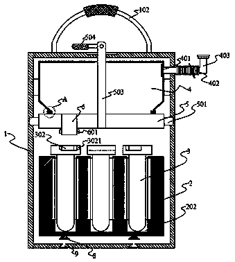
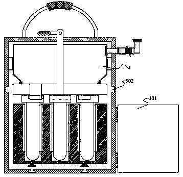
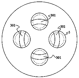
[0032] The waste sorting and collecting device in industrial production of the present invention comprises a housing 1, a door panel 101 is hinged on the side wall of the lower end of the housing 1, a handle 102 is provided at the upper end of the housing 1, and a handle 102 is provided at the lower end of the housing 1. There is a placement frame 2, and the placement frame 2 is provided with a plurality of annularly arranged placement holes 202, and a collection barrel 3 is arranged in the placement hole 202, and the upper end of the annular arrangement of collection barrels 3 is provided with a combination to form an annular chute 302. The upper end of the housing 1 is provided with a collecting cover 4, the collecting cover 4 is provided with a liquid inlet 401, and the lower end of the collecting cover 4 is rotatably connected with a rotating plate 5, and the rotating plate 5 is provided with a connection with the collecting cover 4. The guide tube 6, the lower end of the g...

Embodiment 2

[0035] This embodiment is further optimized on the basis of Embodiment 1 as follows: the side wall of the chute 302 is provided with a guide groove 3021, and the outer wall of the guide tube 6 is provided with a guide block that matches the guide groove 3021 601.

[0036] After adopting this technical scheme, the guide groove 3021 cooperates with the guide block 601 to ensure the stability of the rotation of the rotation plate 5 when the rotation plate 5 is rotated by the handle 504, and the guide tube 6 will not break away from the chute 302, ensuring The waste liquid directly enters the collection barrel 3 without the waste liquid getting out of the collection barrel 3 .

Embodiment 3

[0038] This embodiment is further optimized on the basis of Embodiment 1 as follows: the upper end of the rotating plate 5 is provided with an annular limiting groove 7, the lower end of the collecting cover 4 extends into the limiting groove 7, the A sealing ring 701 is provided between both sides of the collection cover 4 and the inner wall of the limiting groove 7 .

[0039] After adopting this technical solution, through the function of the sealing ring 701, it is ensured that the waste liquid in the collection cover 4 will not enter the collection bucket 3 through the gap between the rotation plate 5 and the lower end of the fixed cover during the rotation of the rotating plate 5 outside.


PUM


Abstract

The invention discloses a waste classifying collecting device in industrial production. The waste classifying collecting device is used for solving the problem that classifying collection of multiplekinds of existing industrial effluent is inconvenient. The waste classifying collecting device comprises a shell, a door plate is hinged to the side wall of the lower end of the shell, and a handle isarranged at the upper end of the shell. A storage rack is arranged at the lower end of the shell, and the storage rack is provided with a plurality of annularly distributed containing holes. Collecting buckets are arranged in the containing holes, sliding grooves combined to form a ring are formed in the upper ends of the collecting buckets arranged annularly, and a collecting cover is arranged at the upper end in the shell. The collecting cover is provided with a liquid inlet, and the lower end of the collecting cover is rotationally connected with a rotary plate. The rotary plate is provided with a guide pipe communicating with the collecting cover, and the lower end of the guide pipe stretches into the sliding groove. An annular groove is formed in the inner wall of the shell, and a rotary block matched with the groove is arranged on the side wall of the rotary plate. The middle of the rotary plate is connected with a rotary rod, and the upper end of the rotary rod penetrates through the outer wall of the shell and then is connected with the handle.

Description

technical field [0001] The invention relates to the field of industrial waste treatment equipment, and more specifically relates to a waste classification collection device in industrial production. Background technique [0002] In the industrial production process, a large amount of waste (solid and liquid) needs to be discharged. In the production workshop, the solid liquid and the waste liquid are generally collected separately, that is, the workshop is generally equipped with a solid collection box and a liquid collection box. The waste liquid is concentrated in a collection pool, and then the collection pool and the waste liquid collection device are connected to each other. The collection device is used as a transportation device to transfer the collected waste liquid to the processing center for disinfection and other follow-up treatment; due to different The waste liquid produced in the workshop is different, and the waste liquid needs to be classified and collected....

Claims


Application Information

Patent Timeline
Patent Type & Authority Applications(China)
IPC IPC(8): B65F1/14B65F1/00
CPCB65F1/006B65F1/14B65F2210/176Y02W30/10
Inventor 沈忠心
Owner 湖州合力环保特材科技有限公司
Why Eureka
Try Eureka