
Device for detecting filtering effect of engine filter element and using method thereof

A technology of filtering effect and engine, applied in jet engine test, gas turbine engine test and other directions, can solve the problems of inaccurate liquid level filling position time, inaccurate start timing time, inability to simultaneously feed liquid and timing principle, etc. The detection efficiency, the use method and the process are stable and reliable, the detection time and the filling end time are accurate

Active Publication Date: 2019-02-19
AECC AERO SCI & TECH CO LTD
View PDF6 Cites 0 Cited by
  • Summary
  • Abstract
  • Description
  • Claims
  • Application Information

AI Technical Summary

Problems solved by technology

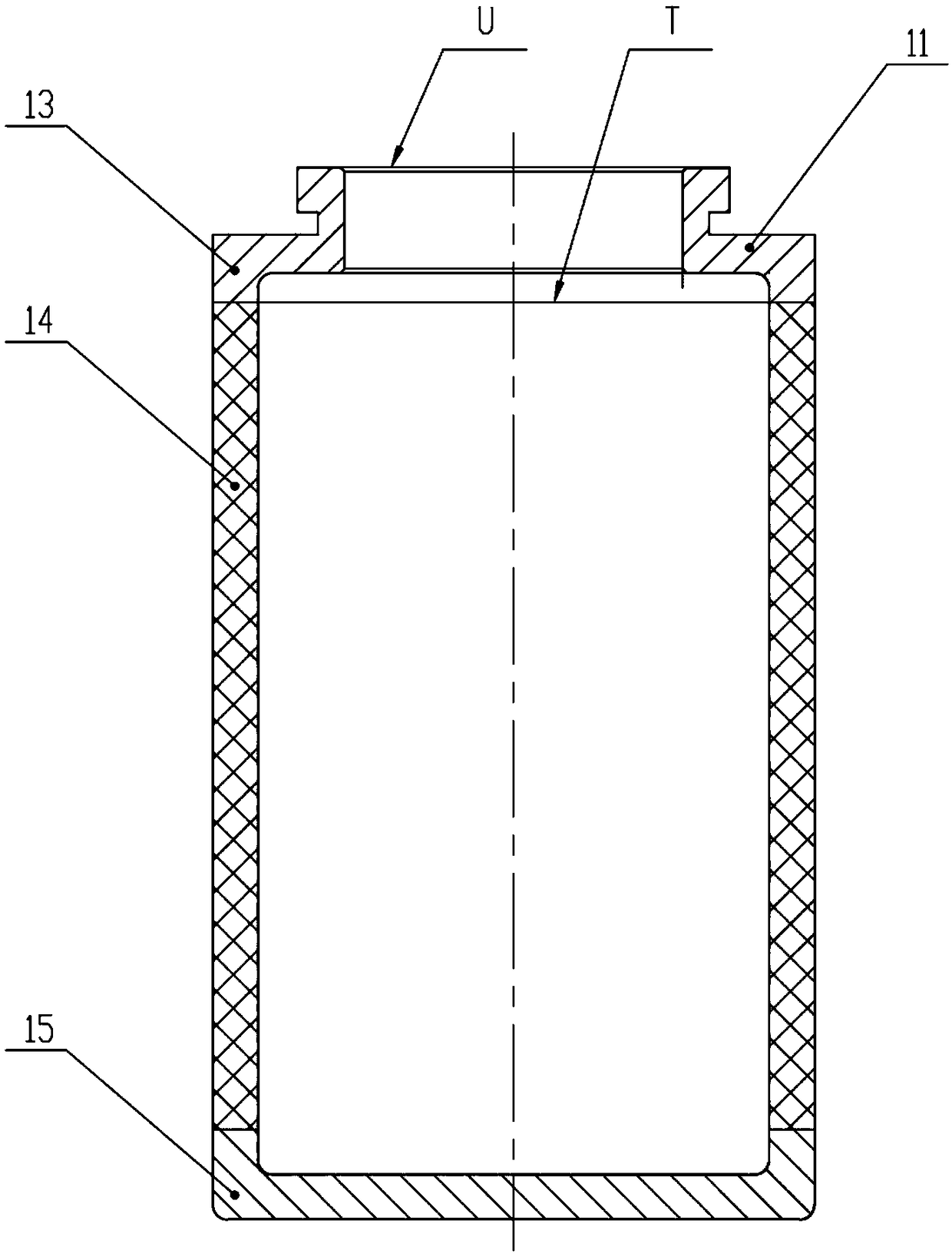
There are two main problems in this kind of direct visual judgment: 1. The start time is not accurate, and it cannot follow the principle of simultaneous liquid filling and timing, and it does not detect under the simulated working state with oil pressure on the periphery; 2. Due to the liquid level is full position in the specified T section of the filter element (such as figure 1 ), not at the U orifice of the filter element (such as figure 1 ), visually judge the time when the liquid level is not full
Therefore, according to the original method, it cannot be accurate and effective and meet the requirements of the simulated working state.

Method used


Image

  • Device for detecting filtering effect of engine filter element and using method thereof
  • Device for detecting filtering effect of engine filter element and using method thereof
  • Device for detecting filtering effect of engine filter element and using method thereof

Examples


Embodiment Construction

[0031] In order to make the purpose, technical solution and advantages of the present invention clearer, the technical solution of the present invention will be described in detail below. Apparently, the described embodiments are only some of the embodiments of the present invention, but not all of them. Based on the embodiments of the present invention, all other implementations obtained by persons of ordinary skill in the art without making creative efforts fall within the protection scope of the present invention.

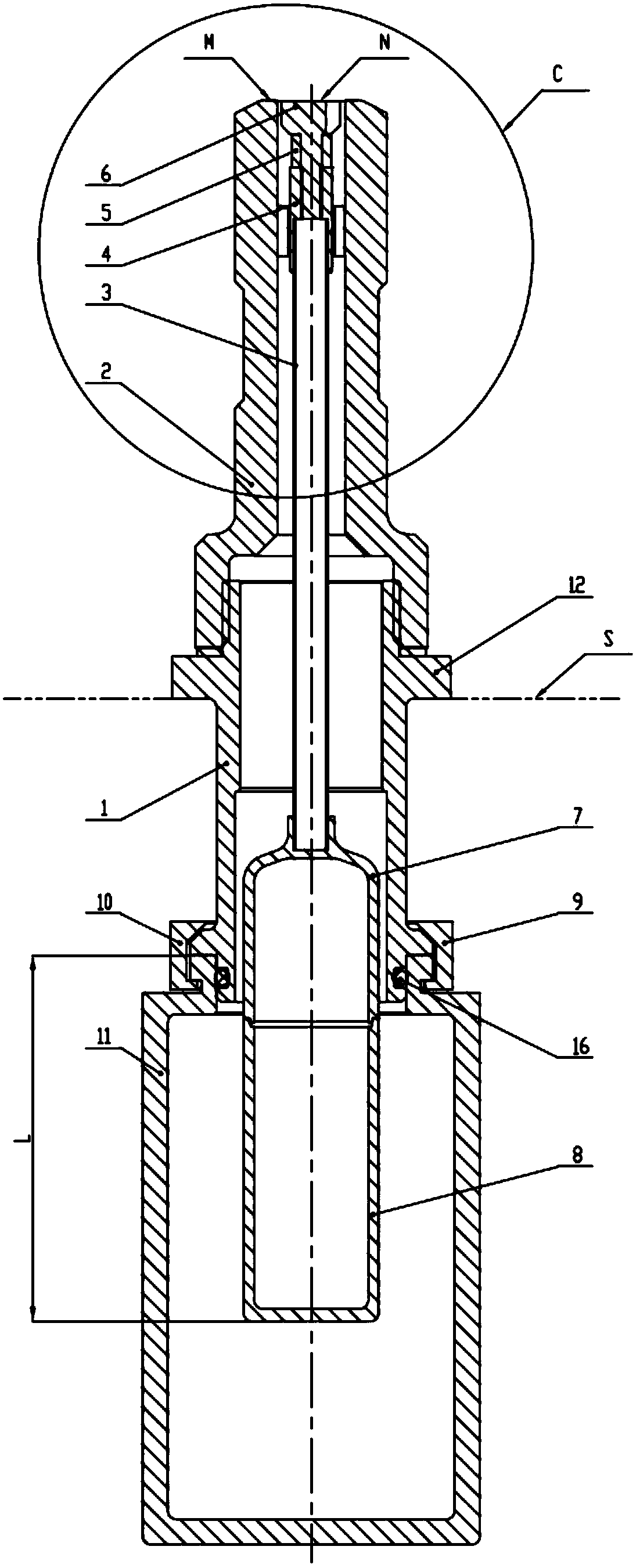
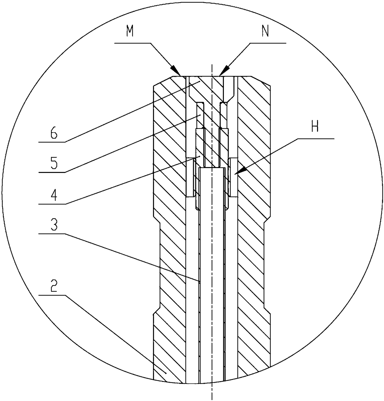
[0032] Examples see Figure 1-Figure 4

[0033] This embodiment provides a device for detecting the filtering effect of an engine filter element, which includes a housing, a signal transmission part and a connecting part. There are openings at both ends of the shell, and a cavity in the middle, and the signal transmission part is arranged in the cavity. When using this embodiment to detect, the oil level signal in the filter element to be tested is transmitte...


PUM


Abstract

The invention provides a device for detecting the filtering effect of an engine filter element and a using method thereof, and relates to the field of assembly detection of aero-engines. The device comprises a shell, a signal transmitting member, and a connector. The using method comprises: immersing the device for detecting the filtering effect of the engine filter element and the connector of the detected filter element in specified oil; detecting the detection start time and the filling end time of the oil flowing into the detected filter element; and comparing the time detection result with the specified required time of the detected filter element. According to the device for detecting the filtering effect of an engine filter element and the using method thereof, the working state ofthe engine filter element can be effectively simulated, the start point-end point can be accurately timed and the liquid level position when the filter element is just filled by using the principle ofsimultaneous liquid inlet simultaneous timing, the detection efficiency is improved, and the protection for the normal operation of the engine is provided.

Description

technical field [0001] The invention relates to the field of assembly detection of aero-engines, in particular to a device for detecting the filtering effect of an engine filter element and a use method thereof. Background technique [0002] The structure of the aero-engine filter core consists of an upper orifice portion 13 (such as figure 1 ) and the middle cylindrical filter body part 14 (such as figure 1 ) and the lower end plug 15 (such as figure 1 ) combined to form a rotary cavity, its function is to filter the impurities in the oil when the engine is working, so as to ensure the continuous and effective operation of the engine. Inevitably, it is necessary to check whether the filtering effect meets the requirements in the assembly or maintenance of the engine. If the filter element is installed on the engine without testing, it will very likely cause insufficient oil supply to the engine, and even cause tragic consequences of machine crash. Therefore, how to simp...

Claims


Application Information

Patent Timeline
Patent Type & Authority Applications(China)
IPC IPC(8): G01M15/14
CPCG01M15/14
Inventor 郭长宝
Owner AECC AERO SCI & TECH CO LTD
Learn More