Automatic despooling and wire cutting device

A kind of equipment and automatic technology, applied in the field of automatic wire pay-off and trimming equipment, can solve the problems of difficult control of wire length and low efficiency, and achieve the effect of high-efficiency and high-precision automatic control

Pending Publication Date: 2019-02-22
DONGGUAN CHAOS ELECTRONICS TECH CO LTD
View PDF0 Cites 3 Cited by
  • Summary
  • Abstract
  • Description
  • Claims
  • Application Information

AI Technical Summary

Problems solved by technology

[0002] At present, the wires on the decorative light bar need to be cut manually. The wires produced and processed are continuous. The wires are sent out by the wire-feeding device, collected in bundles and then cut manually. However, this method is inefficient, and the wires cut manually The length is difficult to control, and in the processing step after cutting the wire, it is necessary to process the soft end between the two cut wires, and then perform steps such as wire stripping and terminal bonding. Therefore, if the wire cutting processing step is to be combined with Subsequent steps work together to complete the automatic processing, and the position of the thread end after the wire is cut also needs to be well controlled. This is a difficult point in completing the automatic cutting operation, so it is urgently needed to improve

Method used


Image

  • Automatic despooling and wire cutting device
  • Automatic despooling and wire cutting device
  • Automatic despooling and wire cutting device

Examples


Embodiment Construction

[0021] The present invention will be further described below in conjunction with accompanying drawing:

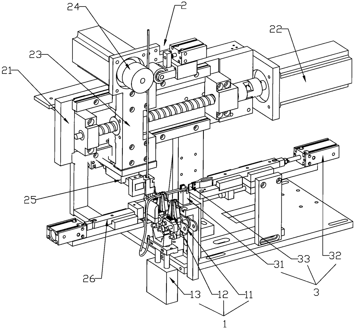
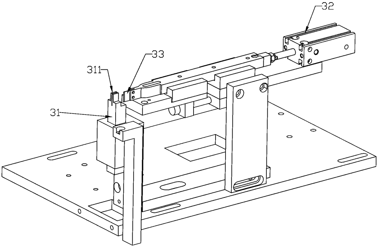
[0022] Such as Figure 1-6 As shown, an automatic wire unwinding and trimming device includes a clamping and conveying module 1, a wire feeding module 2 and a wire cutting module 3;

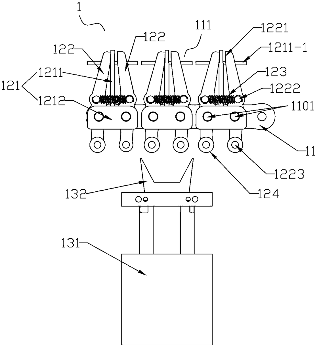
[0023] The clamping conveying module 1 includes a conveyor belt 11 transported from back to front, several clamping devices 12 uniformly installed on the conveyor belt 11 and a control device 13; the conveyor belt 11 has a trimmer Work station 111; the clamping device 12 includes a clamping plate 121 installed on the conveyor belt 11, clamps 122 connected to the front and rear sides of the clamping plate 121, and an elastic element 123 installed between the two clamping clamps 122; the clamping The upper end of the head 122 has a clamping surface 1221; the elastic element 123 tightens the clamping head 122 to press the clamping surface 1221 on the upper end of the clamping head 122 against th...


PUM


Abstract

The invention provides an automatic despooling and wire cutting device which comprises a wire clamping and conveying module, a wire feeding module and a wire cutting module. The wire clamping and conveying module comprises a conveyor belt for conveying from back to front, multiple wire clamping devices uniformly distributed on the conveyor belt, and a control device; a wire cutting station is arranged on the conveyor belt; the control device is arranged under the wire cutting station and controls the wire clamping devices to clamp a wire; the wire cutting module comprises a wire winding blockarranged on the right side of the wire cutting station, and a first drive device and a cutter arranged on the right side of the wire winding block; the wire bypasses the wire winding block and is cutoff through the cutter; the wire feeding module comprises a wire feeding assembly, a wire pulling assembly and a wire pressing assembly; and the wire feeding assembly is used for feeding the wire, thewire pulling assembly controls the moving direction of the wire, and the wire pressing assembly fixes one end of a point, so that the wire is conveyed. The automatic despooling and wire cutting device provided by the invention is high in efficiency, high in processing accuracy, capable of automatically despooling and wire cutting, and convenient to continuously process the follow-up steps.

Description

technical field [0001] The invention relates to the technical field of wire cutting equipment, in particular to an automatic wire-paying and wire-cutting equipment. Background technique [0002] At present, the wires on the decorative light bar need to be cut manually. The wires produced and processed are continuous. The wires are sent out by the wire-feeding device, collected in bundles and then cut manually. However, this method is inefficient, and the wires cut manually The length is difficult to control, and in the processing step after cutting the wire, it is necessary to process the soft end between the two cut wires, and then perform steps such as wire stripping and terminal bonding. Therefore, if the wire cutting processing step is to be combined with Subsequent steps work together to complete the automatic processing, and the position of the thread end after the wire is cut also needs to be well controlled. This is a difficult point in completing the automatic cutti...

Claims


Application Information

Patent Timeline
Patent Type & Authority Applications(China)
IPC IPC(8): B21F11/00B21F23/00
CPCB21F11/00B21F23/00
Inventor 蔡春生
Owner DONGGUAN CHAOS ELECTRONICS TECH CO LTD
Why Eureka
Try Eureka