Automatic tin wire feeding device for laser welding

A technology of laser welding and tin wire feeding, which is applied in the direction of tin feeding devices, welding equipment, metal processing equipment, etc., can solve the problems of tin wire jamming and angle limitation, and achieve the solution of wire jamming and stress deformation Effect

Pending Publication Date: 2019-02-22
威克锐光电科技(苏州)有限公司
View PDF0 Cites 8 Cited by
  • Summary
  • Abstract
  • Description
  • Claims
  • Application Information

AI Technical Summary

Problems solved by technology

[0003] The technical problem mainly solved by the present invention is to provide an automatic tin wire feeding device for laser welding, whi

Method used


Image

  • Automatic tin wire feeding device for laser welding

Examples


Embodiment Construction

[0021] The preferred embodiments of the present invention will be described in detail below in conjunction with the accompanying drawings, so that the advantages and features of the present invention can be more easily understood by those skilled in the art, so as to define the protection scope of the present invention more clearly.

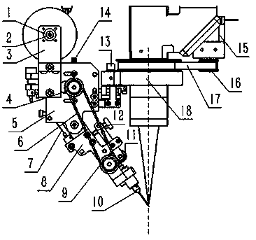
[0022] see figure 1 , the embodiment of the present invention includes:

[0023] An automatic tin wire feeding device for laser welding, comprising: a wire feeding mechanism and a welding rotation mechanism, the wire feeding mechanism is composed of a tin wire fixing device, a tin wire driving device, a tin wire guiding device, and a tin wire pressing adjustment device , the tin wire fixing mechanism is connected to the tin wire transmission mechanism through the first connecting block 5;

[0024] The tin wire fixing mechanism includes: a fixed seat 3, a rotary bearing 1 and a fixed pin 2, the rotary bearing 1 is sleeved in the fixed pin 2, and ...


PUM


Abstract

The invention discloses an automatic tin wire feeding device for laser welding. The automatic tin wire feeding device comprises a wire feeding mechanism and a welding rotating mechanism, wherein the wire feeding mechanism is formed by connecting a tin wire fixing device, a tin wire transmission device, a tin wire guide device, and a tin wire pressing regulating device; the welding rotating mechanism is fixedly connected with the wire feeding mechanism through a lifting mechanism; after the welding head centre line of the welding rotating mechanism is superposed with the centre line of a seconddriven wheel, the welding rotating mechanism and a wire feeding nozzle outlet are positioned on the same welding position. In this way, when the wire feeding mechanism has an angle of deflection, thewire outlet position is ensured to be kept consistent with a laser welding spot all the time; and moreover, wire feeding resistance can be prevented from being too great, stress deformation generatedby a tin wire during wire feeding is avoided, and a wire blocking phenomenon further can be prevented.

Description

technical field [0001] The invention relates to the field of laser welding, in particular to an automatic tin wire feeding device for laser welding. Background technique [0002] The most commonly used laser soldering methods include laser automatic tin wire feeding welding, laser solder paste welding, and laser spray tin ball welding. When the temperature of the plate reaches the melting temperature of the tin wire, the tin wire device sends the tin wire to the pad, the tin wire melts and adheres to the pad, the tin wire is withdrawn, and the welding position continues to keep warm, so that the liquid tin flows to the bottom of the pad , and finally complete the welding. However, in the actual operation process, there will be wire jams in tin wire welding, and there are problems of consistency and adjustability when feeding tin wires that need to be solved. Contents of the invention [0003] The technical problem mainly solved by the present invention is to provide an au...

Claims


Application Information

Patent Timeline
IPC IPC(8): B23K1/005B23K3/06
CPCB23K1/0056B23K3/063
Inventor 朱国栋黄甲张云钊杨胜
Owner 威克锐光电科技(苏州)有限公司
Why Eureka
Try Eureka