Charging pile for new energy automobile

A technology of new energy vehicles and charging piles, applied in electric vehicle charging technology, charging stations, electric vehicles, etc., can solve the problems of damaged charging lines, heavy charging lines, and reducing heat dissipation of batteries, so as to improve service life and reduce temperature Effect

Active Publication Date: 2019-02-22
泰州市扬帆车件有限公司
View PDF7 Cites 9 Cited by
  • Summary
  • Abstract
  • Description
  • Claims
  • Application Information

AI Technical Summary

Problems solved by technology

[0003] In related technologies, the fast charging technology of new energy vehicles is becoming more and more mature, and the car battery can be fully charged in just a few minutes. However, the matching battery heat dissipation technology has not been improved synchronously, and the battery heating caused by fast charging is a serious problem. , which greatly affects the working life of the car battery. At the same time, the chassis of the car will stick to mud and dust when the car is running. Great impact, in severe cases, it will cause the car to spontaneously ignite
[0004] In the existing charging piles, after the charging is completed, the charging wires need to be put back into the charging piles artificially, but the charging wires are generally heavy, which brings great inconvenience to the users
In addition, the charging cable is exposed outside the charging pile, and there is a risk of the charging cable being crushed and damaged by the electric vehicle; in addition, because the charging voltage of the charging pile of the electric vehicle is high, if the power supply is not disconnected, if the charging connector is touched by a child , an electric shock accident will occur

Method used


Image

  • Charging pile for new energy automobile
  • Charging pile for new energy automobile
  • Charging pile for new energy automobile

Examples


Embodiment 1

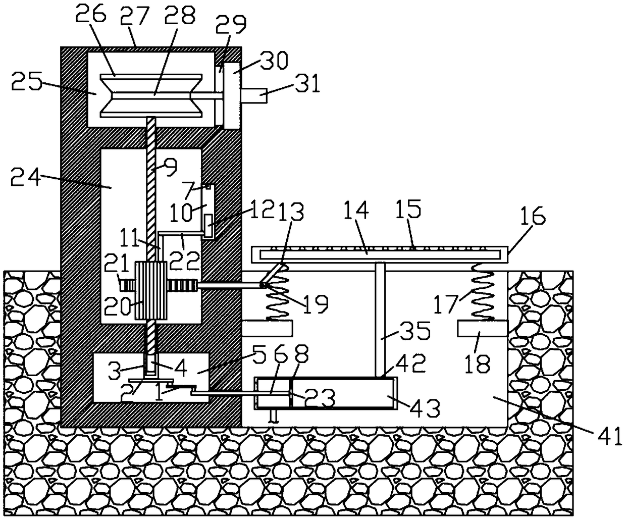
[0024] refer to Figure 1-4 , a charging pile applied to new energy vehicles, including a groove 41 arranged on the upper end surface of the ground and a charging pile housing 27 arranged on the inner bottom of the groove 41 on the left side, and the left and right inner walls of the groove 41 are fixedly connected There is a fixed block 18, a pedal 16 is arranged above the groove 41, and the pedals 16 are respectively elastically connected to the upper ends of the fixed block 18 through springs 17, and the inner wall of the groove 41 is fixed with a limit plate that prevents the pedal 16 from rotating into the groove 41 , the first device cavity 25, the second device cavity 24 and the third device cavity 5 are arranged in the charging pile housing 27 in sequence along the vertical direction, and the second device cavity 24 is provided with a threaded rod 9, and the upper end of the threaded rod 9 runs through The inner top of the second device chamber 24 extends into the firs...

Embodiment 2

[0031] refer to Figure 5 , the inner wall of the groove 41 is fixedly connected with the pump 36, the push rod of the pump 36 penetrates the side wall of the charging pile housing 27 and extends into the third device cavity 5 and is connected to the lower end of the first connecting rod 1 for rotation. The output end of the air cylinder 36 is connected with an expansion air bag 37, and the inner bottom of the groove 41 is fixedly connected with a water storage tank 40 close to the inner wall on the right side. Air enters the fourth one-way valve 39 of the water tank, the upper end of the water storage tank 40 communicates with the cavity 14 through the conduit 38 , and the lower end of the conduit 38 extends to the inner bottom of the water storage tank 40 .

[0032] In this embodiment, the rotating wheel 2 drives the push rod of the air pump 36 to move back and forth through the first connecting rod 1, and then inflates the inflatable air bag 37 through the air pump 36, and ...


PUM


Abstract

The invention discloses a charging pile for a new energy automobile. The charging pile comprises a groove and a charging pile shell, wherein the groove is formed in the upper end face of the ground, and the charging pile shell is arranged at the bottom inside the groove. Fixing blocks are fixedly connected to the opposite left inner wall and the right inner wall of the groove correspondingly. A tread plate is arranged above the groove and elastically connected to the upper ends of the fixing blocks through springs. A first device cavity, a second device cavity and a third device cavity are sequentially formed in the charging pile shell in the vertical direction. The second device cavity is internally provided with a threaded rod. The upper end of the threaded rod penetrates the top insidethe second device cavity and extends into the first device cavity. The threaded rod is in threaded connection with the top inside the second device cavity. A rotating shaft is rotatably connected to the top inside the third device cavity. By means of the charging pile, the problem that a child touches a charging head to cause an electric shock accident is effectively prevented; water is continuously sprayed to a chassis of the automobile for cooling; the temperature of a battery is effectively lowered in the charging process; and the service life of the battery of the new energy automobile isprolonged.

Description

technical field [0001] The invention relates to the technical field of new energy charging equipment, in particular to a charging pile applied to new energy vehicles. Background technique [0002] As the global energy crisis continues to aggravate and environmental pressure continues to increase, new energy vehicles have received widespread attention and attention from the international community, especially the huge impact of the international financial crisis on the automobile industry, driving countries around the world to accelerate the strategic transformation of transportation energy, New energy vehicles have become an important direction for future automotive development. [0003] In related technologies, the fast charging technology of new energy vehicles is becoming more and more mature, and the car battery can be fully charged in just a few minutes. However, the matching battery heat dissipation technology has not been improved synchronously, and the battery heatin...

Claims


Application Information

Patent Timeline
Patent Type & Authority Applications(China)
IPC IPC(8): B60L53/31B60L53/14B60S3/04
CPCB60S3/04Y02T10/70Y02T10/7072Y02T90/12Y02T90/14
Inventor 张冰冰
Owner 泰州市扬帆车件有限公司
Why Eureka
Try Eureka