[0025] The technical solution of this patent will be described in further detail below in conjunction with specific embodiments.
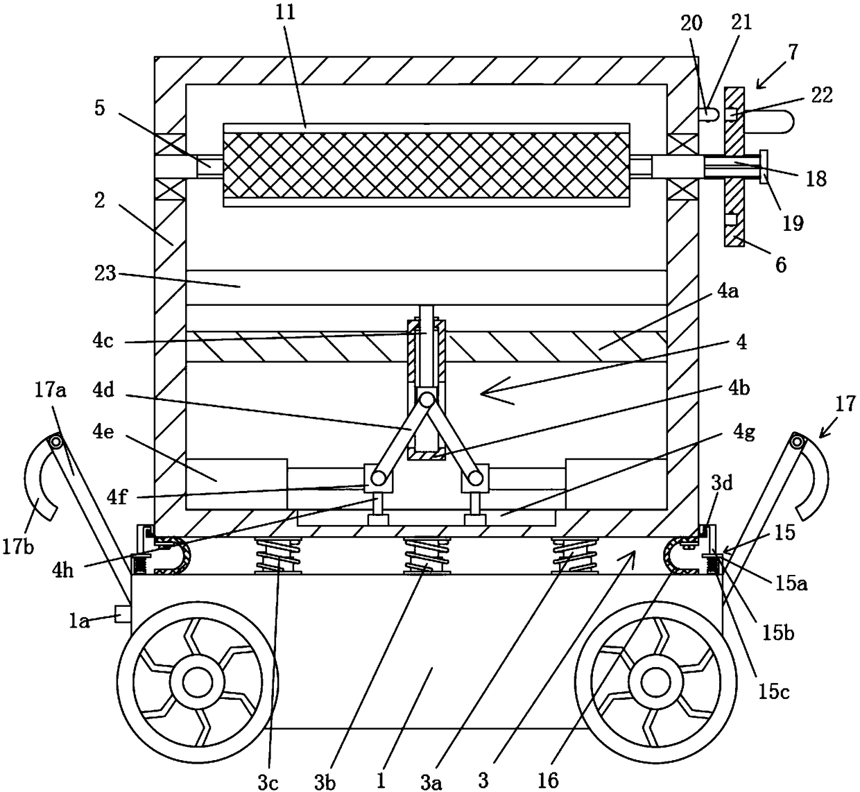
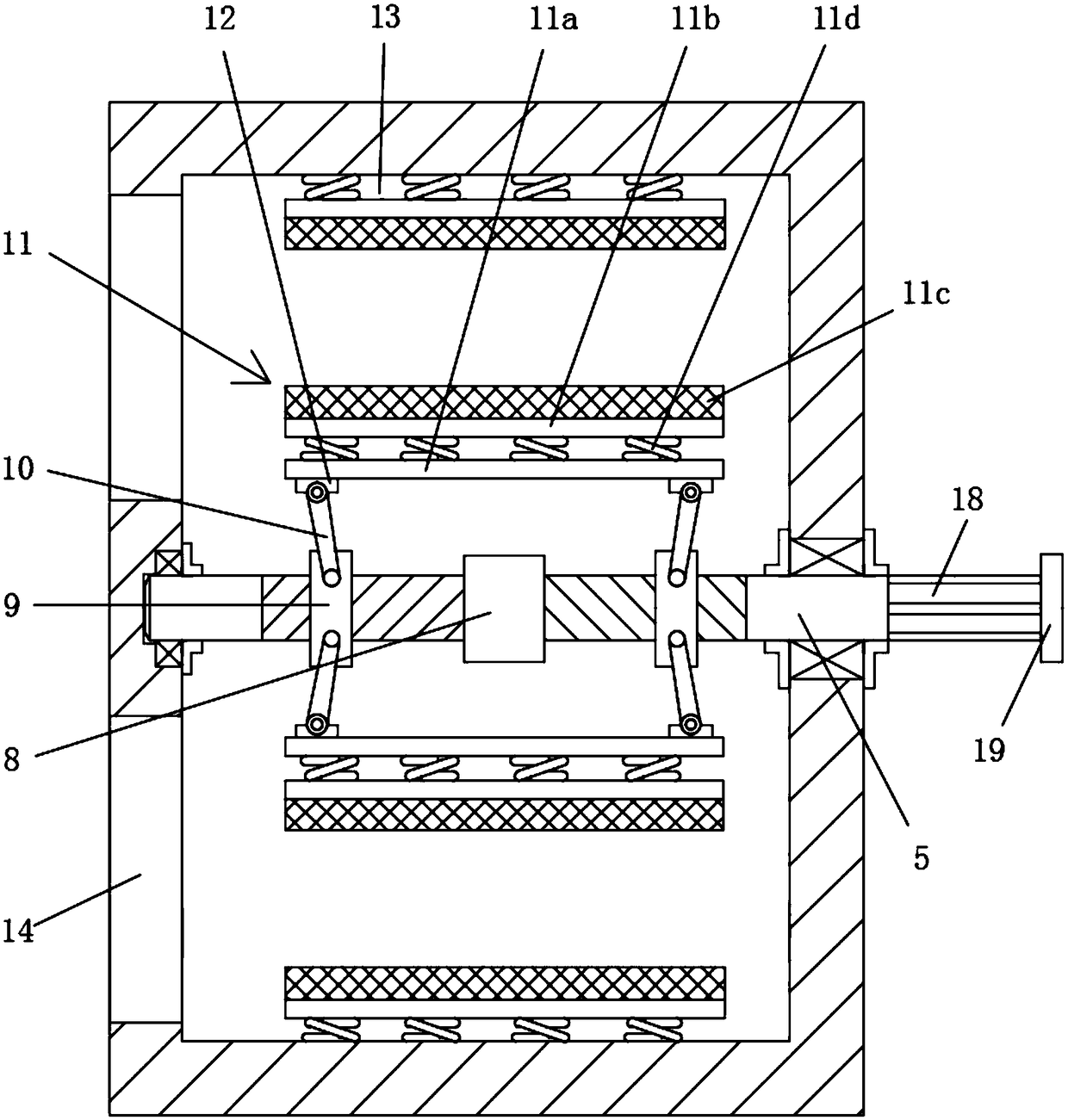
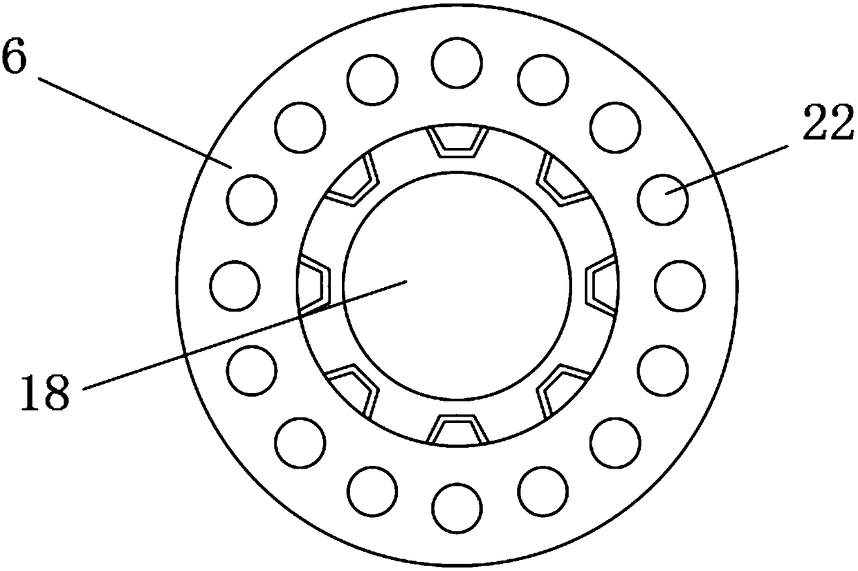
[0026] See Figure 1-3 , A self-propelled material lifting and transportation device, comprising a walking chassis 1, a lidar sensor 1a is provided on the walking chassis 1, and a control unit is connected to the lidar sensor 1a, characterized in that the walking chassis 1 is provided with a transport Box 2, a damping mechanism 3 is provided between the walking chassis 1 and the transport box 2; the walking chassis 1 is connected to the control unit; in this embodiment, the damping mechanism 3 is distributed outside the transport box 2 A number of guide posts 3a at the bottom, a guide sleeve 3b arranged on the walking chassis 1 and sleeved in a one-to-one correspondence with each guide post 3a, and a guide sleeve 3b sleeved on the periphery of the guide post 3a and the guide sleeve 3b and sandwiched between the transport box 2 and the walking chassis 1 is composed of the first buffer spring 3c;
[0027] A number of positioning slots 3d are distributed along the circumferential direction at the lower end of the side wall of the transport box 2. In order to provide an elastic positioning mechanism 15 corresponding to each positioning slot 3d on the traveling chassis 1, specifically, in this embodiment Wherein, the elastic positioning mechanism 15 consists of a positioning frame 15a provided on the walking chassis 1, a positioning bolt 15b passing through the positioning frame 15a along the vertical direction from bottom to top, and a positioning frame set on the lower side of the positioning frame 15a. The positioning spring 15c on the periphery of the bolt 15b is composed of a positioning hook 15d fixed on the upper end of the positioning bolt 15b and matched with the positioning slot 3d; the positioning hook 15d is hooked into the positioning slot 3d under the action of the positioning spring 15c, elastic The positioning mechanism 15 cooperates with the positioning slot 3d to form a detachable fixed structure connecting the transport box 2 and the traveling chassis 1. The traveling chassis 1 is connected to the control unit. When the transport box needs to be disassembled, it is only necessary to remove the positioning hook from the positioning card slot, which is convenient and quick to operate.
[0028] At the same time, in order to prevent dust from entering between the walking chassis 1 and the transport box 2, a dust-proof film 16 is provided along the circumferential direction on the outer bottom edge of the transport box 2. The dust-proof film 16 is fixed on the bottom of the transport box 2 through a pressure plate and screws; When the box 2 is in a static state, the dustproof film 16 is U-shaped under the squeezing of the transport box 2 and the walking chassis 1.
[0029] A lifting platform 23 is provided in the transport box 2, and a lifting drive mechanism 4 is provided in the transport box 2 below the lifting platform 23; in this embodiment, the lifting drive mechanism 4 is provided under the lifting platform 3 and is connected to the transport box. 2 A fixed support plate 4a connected to the inner wall, a lifting bearing frame 4b that is vertically inserted in the fixed support plate 4a, and a lifting support rod arranged on the bottom surface of the lifting platform 3 in the vertical direction and movably sleeved with the lifting bearing frame 4b 4c. Two lifting drive rods 4d coaxially hinged on the proximal end of the lower end of the lifting support rod 4c, two hydraulic cylinders 4e arranged symmetrically at the bottom of the transport box 2 and respectively arranged at the free end of the piston rod of the hydraulic cylinder 4e and corresponding to The transitional connecting block 4f hinged at the proximal free end of the lifting drive rod 4d, the T-shaped chute 4g which is parallel to the movement direction of the piston rod of the hydraulic cylinder 4e and is arranged at the bottom of the transport box 2, and is movably arranged in the T-shaped chute 4g And it is composed of a guide support sliding block 4h connected with the transition connecting block 4f; the lifting bearing frame 4b is provided with a relief hole on the side wall corresponding to the lifting driving rod 4d; the hydraulic cylinder 4e and the hydraulic station on the walking chassis 1 Pipeline connection, a screw rod 5 is installed in the horizontal direction in the transport box 2 above the lifting platform 23, the contact part of the screw rod 5 and the transport box 2 is provided with a bearing, one end of the screw rod 5 extends through the transport box 2 to the outside , An operating handle 6 is provided at the end of the screw rod 5 located outside the transport box 2, and the operating handle 6 is connected with a positioning mechanism 7;
[0030] Specifically, in this embodiment, the positioning mechanism 7 includes a spline shaft 18 arranged on the free end of the screw rod 5 outside the transport box 2, and the operating handle 6 is movably sleeved on the spline shaft 18, The free end of the shaft 18 is provided with a limit block 19; a positioning post 20 is provided on the outer wall of the transport box 2 corresponding to the operating handle 6, and a ball screw 21 is provided on the outer wall of the positioning post 20. The side of the operating handle 6 is evenly distributed in the circumferential direction. A number of positioning grooves 22 corresponding to the positioning posts 20 are provided in the positioning grooves 22 with positioning grooves 22 matched with balls on the ball screw 21. During transportation, the operating handle 6 is fixed.
[0031] The screw rod 5 located in the transport box 2 is provided with an isolating ring 8 in the middle. The screw threads on the screw rods 5 on both sides of the isolating ring 8 are in opposite directions. The screw rods 5 on both sides of the isolating ring 8 are threaded with internal thread sleeves 9, A linkage rod 10 is hinged on the internal threaded sleeve 9, and a first clamping plate 11 is respectively arranged on both sides of the screw rod 5 in the horizontal direction. Specifically, in this embodiment, the first clamping plate 11 is driven by The plate 11a, a support plate 11b arranged on the outer side of the drive plate 11a, a rubber pad 11c arranged on the outer end surface of the support plate 11b, and a number of second buffer springs 11d arranged between the drive plate 11a and the support plate 11b; The springs 11d are respectively fixedly connected to the drive plate 11a and the support plate 11b; the hinge seat is arranged on the drive plate 11a, and the two ends of the first clamping plate 11 opposite to the screw rod 5 in the length direction are respectively provided with hinge joints Seat 12, the free end of the linkage rod 10 is hinged to the corresponding hinge seat 12, and a second clamping plate 13 that cooperates with the first clamping plate 11 to clamp the material is provided on the inner wall of the transport box 2; Two operation ports 14 are provided on the side wall of the transport box 2 on one side, and each operation port 14 is located on the side of the second clamping plate 15.
[0032] Further, in order to prevent the walking chassis 1 from colliding during movement, an anti-collision buffer mechanism 17 is provided on the outer walls of both ends of the walking chassis 1 in the walking direction. The anti-collision buffer mechanism 17 is provided by the anti-collision buffer mechanism provided on the walking chassis 1. The support rod 17a and the arc-shaped anti-collision buffer spring piece 17b elastically hinged on the anti-collision support rod 17a are composed.
[0033] It should be noted that, in this embodiment, the walking chassis is the prior art, so the structure is not repeated here. At the same time, the connection between the control unit and the existing devices such as the walking chassis, the lidar sensor and the hydraulic cylinder is also an existing technology. It is not what the present invention wants to protect. I will not repeat them here again.
[0034] The working principle of the present invention is: according to the size of the material to be transported, use the control unit to activate the hydraulic cylinder to adjust the height of the lifting platform, put the material to be transported into the lifting platform in the transport box through the operating port, and then turn the operating handle, Driven by the screw rod, the first clamping plate approaches the second clamping plate to clamp the material on the lifting platform. After the initial clamping, push the operating handle to make the positioning groove approach the positioning column, and then continue to rotate The handle is operated to make the second buffer spring elastically deform. At this time, the corresponding positioning groove is sleeved on the positioning column to complete the fixing of the operation handle. Then start the walking chassis through the control unit, and move to the destination by itself with the cooperation of the lidar sensor and the navigation map built into the control unit. When forward or backward is obstructed, the arc-shaped anti-collision buffer shrapnel will buffer to avoid damage to the device.
[0035] The preferred embodiments of this patent are described in detail above, but this patent is not limited to the above embodiments. It can also be made without departing from the purpose of this patent within the scope of knowledge possessed by those of ordinary skill in the art. Various changes.