Underground coal mine hydraulic oriented roof cutting equipment and construction method thereof

A hydraulic and coal mine technology, applied in coal mine underground hydraulic directional roof cutting equipment and its construction field, can solve problems such as difficult support, large blast shock wave disturbance, complicated procedures, etc., achieve low operation and maintenance costs, and few use restrictions , The effect of simple construction technology

Pending Publication Date: 2019-02-22
中煤能源研究院有限责任公司
View PDF0 Cites 4 Cited by
  • Summary
  • Abstract
  • Description
  • Claims
  • Application Information

AI Technical Summary

Problems solved by technology

Blasting roof cutting technology, the disturbance generated by the blasting shock wave is large, which affects the stability of the roadway, the blasting produces more toxic and harmful gases, and there is a risk of dumb guns, high safety risks, and there are many uncertainties in the blasting roof cutting. The key parameters of inclination and inclination often require downhole tests, and the evacuation of personnel is required during the blasting, which is time-consuming and laborious, which affects the work progress to a certain extent and causes tension in the working face. Moreover, as explosives are controlled commodities, the procurement and transportation are very strict and the procedures are complicated.
Hydraulic roof cutting technology has a wide range of applications, but hydraulic fracturing technology causes a large increase in water content in the roof of the working face. For mines where the roof and floor are made of mudstone, which is easy to swell and collapse when exposed to water, it is not conducive to the management of the working face and roadway roof. Difficulties, which seriously affect downhole production

Method used


Image

  • Underground coal mine hydraulic oriented roof cutting equipment and construction method thereof
  • Underground coal mine hydraulic oriented roof cutting equipment and construction method thereof
  • Underground coal mine hydraulic oriented roof cutting equipment and construction method thereof

Examples


Embodiment Construction

[0030] The present invention will be further described below in conjunction with the accompanying drawings.

[0031] Coal mine A adopts gob-side entry retaining technology, and concrete walls are used as roadside support. Coal mine A mines 8 coals, with an average thickness of 3.2m, a near-horizontal coal seam, and a buried depth of about 700m. It belongs to a high-gas mine. Along the trough, they are respectively the transport trough and the return air trough, and gob-side entry is carried out for the transport trough. Roof cutting technology is used to reduce the pressure of gob-side entry retention. The thickness of the wall beside the lane is 1.0m, and the height is 3.2m.

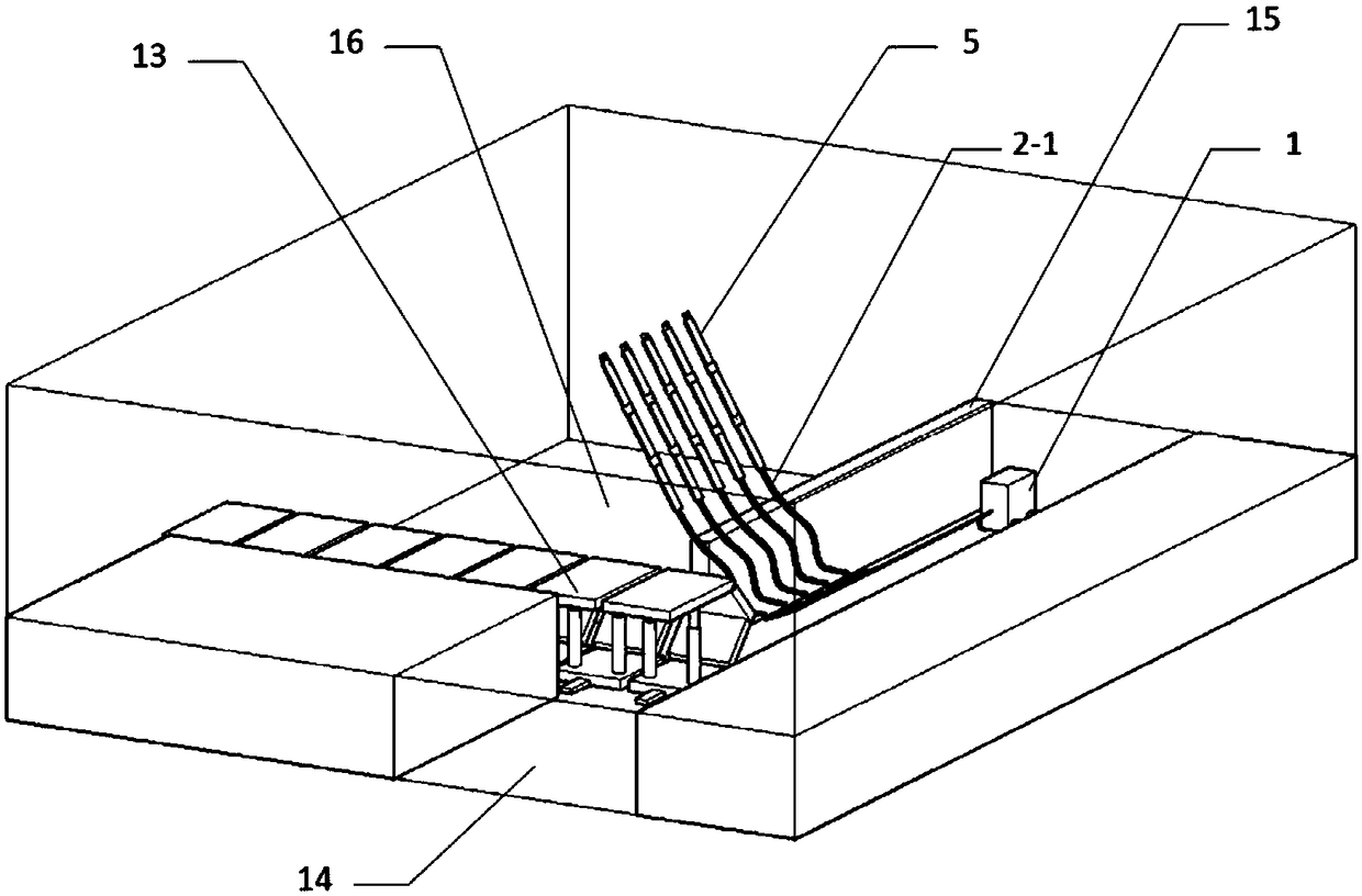
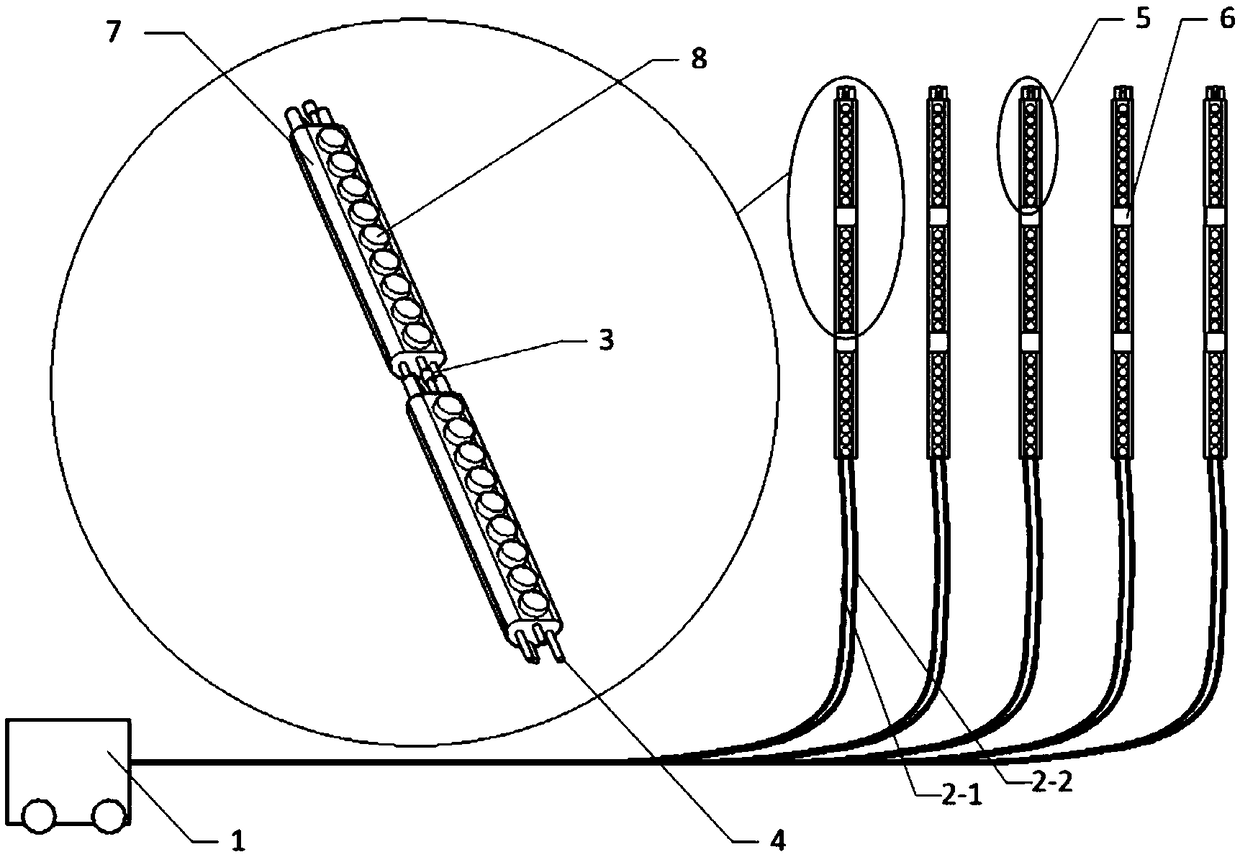
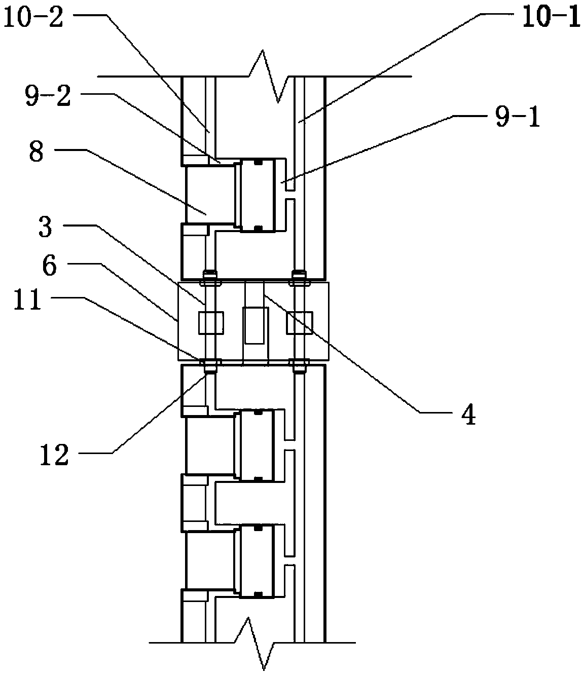
[0032] Such as Figure 1 to Figure 4 As shown, the coal mine underground hydraulic directional roof cutting equipment provided by the present invention is composed of 1 explosion-proof pump station 1, 5 liquid inlet long pipes 2-1, 5 liquid return long pipes 2-2 and N side thrusters, Explosion-proof ...


PUM


Abstract

The invention discloses underground coal mine hydraulic oriented roof cutting equipment and a construction method thereof. The equipment mainly comprises an anti-explosion pump station, liquid feedinglong tubes, liquid returning long tubes and lateral thrusters, wherein each lateral thruster consists of a plurality of lateral thrusting bars which are connected in series through connecting tubes and connecting rods; and a plurality of hydraulic jacks are arranged on one side of each lateral thrusting bar. The construction method using the equipment comprises the steps of during construction, drilling holes through an advance face, mounting the lateral thrusters in the drilled holes through a lagging face, providing hydraulic force for the lateral thrusters by the anti-explosion pump station, carrying out lateral thrusting by the hydraulic jacks while liquid is fed by the liquid feeding long tubes so as to generate huge thrust to split off top rock of a free face to cut a roof and reduce pressure of surrounding rock of a goaf side; and stopping liquid supplying of the liquid feeding long tubes and releasing pressure, supplying liquid by the liquid returning long tubes, and withdrawing the hydraulic jacks. The underground coal mine hydraulic oriented roof cutting equipment can be used for the fields of coal mine roof cutting and pressure releasing, non-pillar mining, prevention and control of rock burst and the like.

Description

technical field [0001] The invention belongs to the field of mining without coal pillars in underground coal mines, and in particular relates to a coal mine underground hydraulic directional top-cutting equipment and a construction method thereof. Background technique [0002] In the application of coal pillarless mining, through the implementation of directional roof cutting technology on the roof, a part of the cantilever beam of the roof is cut off, which reduces the pressure brought by the roof, improves the stability of the surrounding rock, and reduces the deformation of the surrounding rock along the goaf. Improve support safety and reduce support costs. At present, blasting technology and hydraulic fracturing technology are mainly used to perform directional roof cutting and pressure relief on the roof. Both are drilled in a row to the roof, and high pressure is generated in the holes, and cracks are generated in the rocks in the adjacent space under the action of t...

Claims


Application Information

Patent Timeline
Patent Type & Authority Applications(China)
IPC IPC(8): E21C37/08
CPCE21C37/08
Inventor 吴玉意郑忠友朱磊刘毅涛王黔张振配王俊峰陈国华宁石杰黄剑斌姚伟
Owner 中煤能源研究院有限责任公司
Why Eureka
Try Eureka