Novel sliding main shaft structure

A main shaft and a new type of technology, used in machines/engines, liquid fuel engines, liquid variable capacity machines, etc., can solve the problems of general tensile strength, complex overall structure, and inflexible use, and achieve high tensile strength and connection. The effect of convenient molding, novel and practical overall structure

Pending Publication Date: 2019-02-22
江苏可奈力机械制造有限公司
View PDF0 Cites 0 Cited by
  • Summary
  • Abstract
  • Description
  • Claims
  • Application Information

AI Technical Summary

Problems solved by technology

[0002] The connection between the main shaft and the plunger of the existing oblique-axis plunger quantitative pump is usually to use a pressure plate to press the plunger ball head into the main shaft ball socket. The overall structure is complex, the use is not flexible enough, and the tensile strength is average.

Method used


Image

  • Novel sliding main shaft structure
  • Novel sliding main shaft structure

Examples


Embodiment Construction

[0013] The present invention will be further described below in conjunction with the accompanying drawings and embodiments.

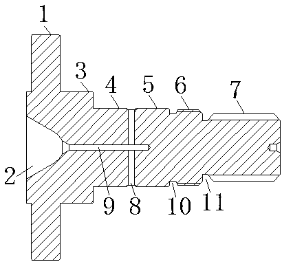
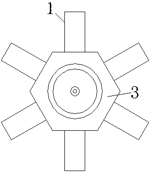
[0014] Such as figure 1 and figure 2 As shown, a novel sliding main shaft structure according to the present invention includes a long axis body and six sliding columns 1 evenly arranged at one end of the long axis body, and the sliding columns 1 are vertically arranged with the long axis body, and the sliding columns A positioning ball socket 2 is provided in the middle of the end face of the long shaft body on one side. The long shaft body includes a sliding column connection section 3, a bearing connection section I4, a bearing connection section II5, a thread section 6 and a spline tooth section 7. The cross-section of the connecting section 3 of the sliding column is a regular hexagon, the cross-sections of the bearing connecting section I4, the bearing connecting section II5, the threaded section 6 and the spline tooth section 7 are all circular...


PUM


Abstract

The invention relates to a novel sliding main shaft structure which comprises a long shaft body and a plurality of sliding columns arranged at one end of the long shaft body. A positioning ball socketis arranged in the middle of the end face of the side, provided with the sliding columns, of the long shaft body, the long shaft body comprises a sliding column connection section, a bearing connection section I, a bearing connection section II, a thread section and a spline tooth section, a lubricating oil hole is formed in the portion, between the bearing connection section I and the bearing connection section II, of the long shaft body, a long hole is formed in the bottom of the positioning ball socket, and the long hole communicates with the lubricating oil hole. The novel sliding main shaft structure is novel in structure, practical, flexible and convenient to use and high in tensile strength.

Description

technical field [0001] The invention relates to a main shaft, in particular to a sliding main shaft for a plunger pump. Background technique [0002] The connection between the main shaft and the plunger of the existing oblique-axis plunger quantitative pump is usually to use a pressure plate to press the plunger ball head into the main shaft ball socket. The overall structure is complex, the use is not flexible enough, and the tensile strength is average. Contents of the invention [0003] Purpose of the invention: The purpose of the invention is to overcome the deficiencies in the prior art and provide a novel sliding spindle structure with novel and practical structure, flexible and convenient use, and high tensile strength. [0004] Technical solution: In order to solve the above technical problems, a new type of sliding spindle structure according to the present invention includes a long shaft body and a number of sliding columns arranged at one end of the long shaft ...

Claims


Application Information

Patent Timeline
Patent Type & Authority Applications(China)
IPC IPC(8): F04B1/14F04B1/16F04B53/18F04B53/00
CPCF04B1/16F04B1/141F04B53/00F04B53/18
Inventor 孙晓浩汤晓滢
Owner 江苏可奈力机械制造有限公司
Why Eureka
Try Eureka