A Double Valve Pneumatic Globe Valve

A pneumatic stop valve and valve technology, applied in the direction of valve details, valve device, valve housing structure, etc., can solve problems such as difficult to confirm whether to open and close, affect production efficiency and production benefits, laborious operation, etc., to achieve simple structure, The effect of saving time and effort in operation and reducing work accidents

Active Publication Date: 2020-05-19
HENAN GUANSHI MASCH EQUIP CO LTD
View PDF5 Cites 0 Cited by
  • Summary
  • Abstract
  • Description
  • Claims
  • Application Information

AI Technical Summary

Problems solved by technology

[0004] The present invention provides a double-valve pneumatic stop valve. The present invention provides a double-valve pneumatic stop valve, which solves the problems of the existing knob-type valves, which are difficult to control, laborious to operate, and difficult to confirm whether opening and closing are realized, which is likely to cause production failure. Accidents, problems affecting production efficiency and production benefits

Method used


Image

  • A Double Valve Pneumatic Globe Valve
  • A Double Valve Pneumatic Globe Valve
  • A Double Valve Pneumatic Globe Valve

Examples


Embodiment 1

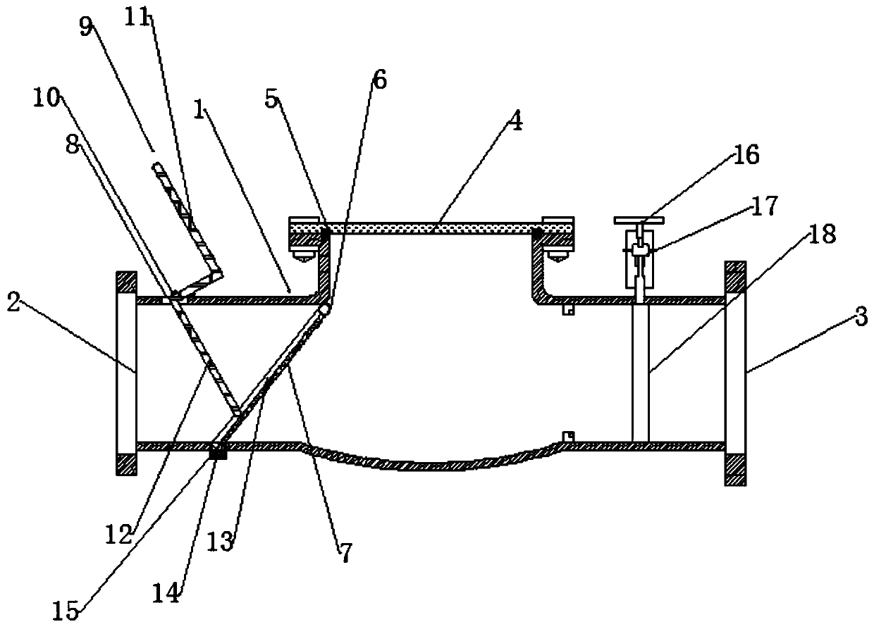
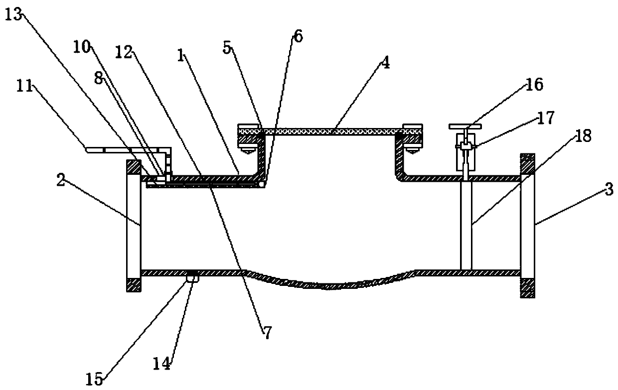
[0026] A double-valve pneumatic globe valve, comprising a valve body 1, the left side of the valve body 1 is fixedly connected with an inlet 2, the right side of the valve body 1 is fixedly connected with an outlet 3, and the top of the valve body 1 is connected by a bolt A bonnet 4 is fixedly connected, and a first sealing ring 5 is arranged between the valve body 1 and the bonnet 4; the inner wall of the inner cavity of the valve body 1 is provided with an ejection-type first valve assembly near the inlet 2, and the valve A second valve assembly is provided near the outlet 3 on the inner wall of the inner cavity of the body 1 .

[0027] Firstly, the double-valve pneumatic shut-off valve of the present invention is fixedly connected to the installed pipeline. When the double-valve pneumatic shut-off valve is opened, the first valve assembly and the second valve assembly are opened, and the material passes through; when the double-valve pneumatic shut-off valve When the valve ...

Embodiment 2

[0029] Based on Embodiment 1, the first valve assembly includes a spring hinge shaft 6 fixedly connected to the inner wall of the valve body 1, a partition plate 7 fixedly attached to the inner wall of the valve body 1 through the spring hinge shaft 6, and the valve body 1. A bracket component that is flexibly connected to the outer wall. The partition 7 is fixed on the inner wall of the valve body 1 through the spring hinge shaft 6. The spring hinge shaft 6 makes the partition 7 always adhere to the inner wall of the valve body 1 without external force; the bracket assembly can be used to push the partition 7 to the partition The side opposite to the inner wall side of the valve body 1 where the plate 7 is located.

Embodiment 3

[0031] Based on Embodiment 2, the bracket assembly includes a through hole 8 provided on the outer wall of the valve body 1 and a bent strut 9 passing through the through hole 8; a folded sealing sleeve 10 is provided at the through hole 8 . The strut 9 passes through the through hole 8, a part of the strut 9 is located inside the valve body 1, and the other part of the strut 9 is exposed to the outside of the valve body 1. The folded sealing sleeve 10 facilitates the position movement of the strut 9 during rotation and prevents the material Escape acts as a seal.


PUM


Abstract

The invention relates to a novel double-valve pneumatic stop valve. The novel double-valve pneumatic stop valve comprises a valve body; the left side of the valve body is fixedly connected with an inlet, and the right side of the valve body is fixedly connected with an outlet; the top of the valve body is fixedly connected with a valve cover through a bolt, and a first sealing ring is arranged between the valve body and the valve cover; and the position, close to the inlet, of an inner cavity of the valve body is provided with an ejection type first valve assembly, and the position, close to the outlet, of the inner cavity of the valve body is provided with a second valve assembly. Through the novel double-valve pneumatic stop valve provided by the invention, the problems that an existingrotary knob type valve is difficult to control and operate, whether opening and closing of the valve are achieved or not is not prone to being determined, production accidents are prone to occurring,and the production efficiency and benefits are influenced are solved.

Description

technical field [0001] The invention relates to the field of pneumatic shut-off valve devices, in particular to a double-valve pneumatic shut-off valve. Background technique [0002] The opening and closing part of the globe valve is a plug-shaped disc, the sealing surface is flat or sea-cone, and the disc moves linearly along the centerline of the valve seat. The movement form of the valve stem, (common name: dark rod), also has a lifting and rotating rod type that can be used to control various types of fluids such as air, water, steam, various corrosive media, mud, oil, liquid metal and radioactive media. flow. Therefore, this type of shut-off valve is very suitable for cutting or regulating and throttling. Because the opening or closing stroke of the valve stem of this type of valve is relatively short, and it has a very reliable cut-off function, and because the change of the valve seat opening is proportional to the stroke of the valve disc, it is very suitable for f...

Claims


Application Information

Patent Timeline
Patent Type & Authority Patents(China)
IPC IPC(8): F16K13/00F16K27/00
CPCF16K13/00F16K27/00
Inventor 管正文
Owner HENAN GUANSHI MASCH EQUIP CO LTD
Why Eureka
Try Eureka