
Air conditioning system and control method thereof

A technology of an air conditioning system and a control method, which is applied to refrigerators, refrigeration components, refrigeration and liquefaction, etc., can solve the problems of compressor suction with liquid, affecting the long-term reliable operation of the compressor, and refrigerant gasification, etc. Energy efficiency, ensuring long-term reliable operation, and reducing power consumption

Active Publication Date: 2019-02-22
ZHUHAI GREE REFRIGERATION TECH CENT OF ENERGY SAVING & ENVIRONMENTAL PROTECTION
View PDF8 Cites 0 Cited by
  • Summary
  • Abstract
  • Description
  • Claims
  • Application Information

AI Technical Summary

Problems solved by technology

[0002] With the development of the refrigeration industry and the improvement of air-conditioning technology, the requirements for compressors are getting higher and higher. The low-frequency operation of the compressor is a major technical difficulty. When the compressor is operated at low frequency, it is easy to cause incomplete evaporation of the refrigerant in the evaporator. As a result, the compressor sucks liquid
Suction with liquid will cause difficulties in the formation of oil film inside the compressor, which will affect the long-term reliable operation of the compressor. On the other hand, suction with liquid will cause the refrigerant to vaporize rapidly inside the compressor, which will seriously affect the performance of the compressor.

Method used


Image

  • Air conditioning system and control method thereof
  • Air conditioning system and control method thereof
  • Air conditioning system and control method thereof

Examples


Embodiment Construction

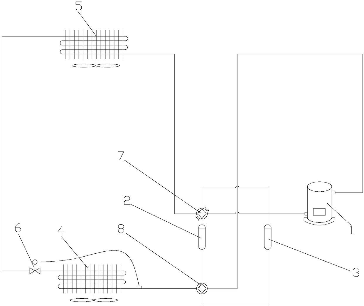
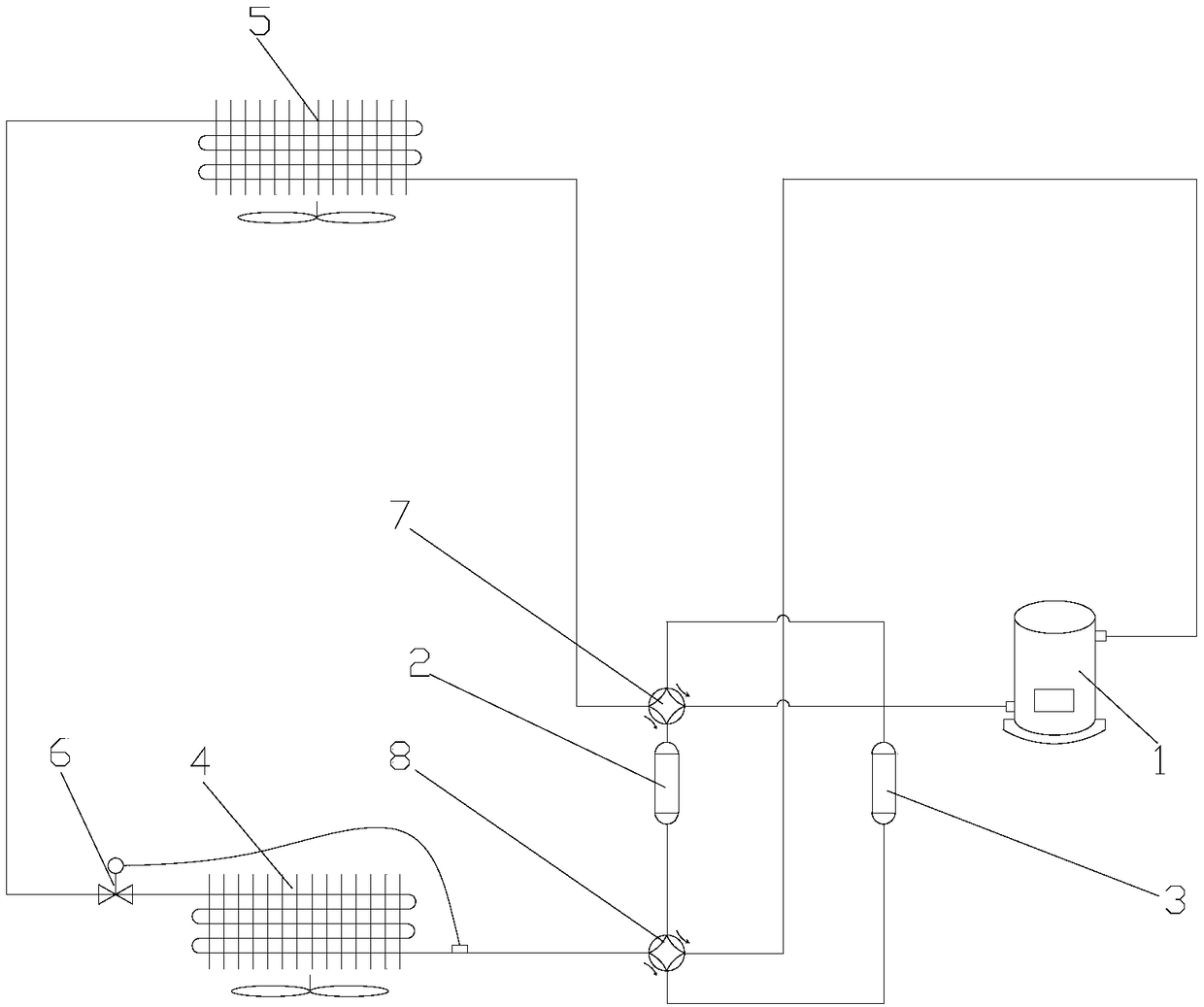
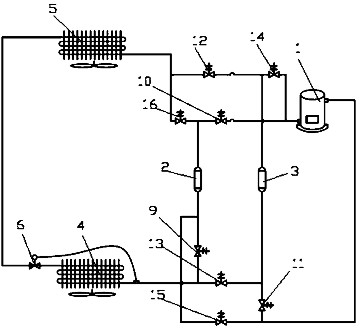
[0031] see in conjunction Figure 1 to Figure 3 As shown, the air conditioning system includes a compressor 1, a first gas-liquid separator 2 and a second gas-liquid separator 3, and the positions of the first gas-liquid separator 2 and the second gas-liquid separator 3 can be switched so that the first When the gas-liquid separator 2 is located at the suction end of the compressor 1, the second gas-liquid separator 3 is located at the discharge end of the compressor 1, and when the first gas-liquid separator 2 is located at the discharge end of the compressor 1, the second gas-liquid separator 3 The separator 3 is located at the suction end of the compressor 1 .

[0032] The positions of the first gas-liquid separator 2 and the second gas-liquid separator 3 can be switched, so when the air conditioning system is working, the liquid level of the gas-liquid separator at the suction end of the compressor 1 can be monitored, and when the liquid level reaches a certain height Fin...


PUM


Abstract

The invention provides an air conditioning system and a control method thereof. The air conditioning system comprises a compressor (1), a first air-liquid separator (2) and a second air-liquid separator (3); the position of the first air-liquid separator (2) and the position of the second air-liquid separator (3) can be switched, so that the second air-liquid separator (3) is located at the air exhaust end of the compressor (1) when the first air-liquid separator (2) is located at the air suction end of the compressor (1), and the second air-liquid separator (3) is located at the air suction end of the compressor (1) when the first air-liquid separator (2) is located at the air exhaust end of the compressor (1). According to the air conditioning system, liquid entrainment during air suction of the compressor can be prevented effectively, so that long-time reliable running of the compressor can be guaranteed.

Description

technical field [0001] The invention belongs to the technical field of air conditioning, and in particular relates to an air conditioning system and a control method thereof. Background technique [0002] With the development of the refrigeration industry and the improvement of air-conditioning technology, the requirements for compressors are getting higher and higher. The low-frequency operation of the compressor is a major technical difficulty. When the compressor is operated at low frequency, it is easy to cause incomplete evaporation of the refrigerant in the evaporator. This causes the compressor to suck liquid. Suction entrainment will cause difficulties in the formation of oil film inside the compressor, affecting the long-term reliable operation of the compressor. On the other hand, inhalation entrainment will cause the refrigerant to vaporize rapidly inside the compressor, which will seriously affect the performance of the compressor. Contents of the invention ...

Claims


Application Information

Patent Timeline
Patent Type & Authority Applications(China)
IPC IPC(8): F25B49/02F25B43/00F25B13/00
CPCF25B13/00F25B43/00F25B49/02Y02B30/70
Inventor 黄康赵旭敏卢林高刘亮董辉
Owner ZHUHAI GREE REFRIGERATION TECH CENT OF ENERGY SAVING & ENVIRONMENTAL PROTECTION
Learn More