Multi-branch indoor heat exchanger for synchronous heat exchange

An indoor heat exchanger and multi-branch technology, used in evaporators/condensers, lighting and heating equipment, refrigeration components, etc., can solve the problems of complex overheating equipment, high processing and manufacturing costs, and no overheating equipment, and achieve enhanced Stability and reliability, stability and safety assurance, the effect of improving heat exchange effect

Active Publication Date: 2015-07-08
NANJING NORMAL UNIVERSITY
View PDF12 Cites 0 Cited by
  • Summary
  • Abstract
  • Description
  • Claims
  • Application Information

AI Technical Summary

Problems solved by technology

[0003]At present, most of the indoor heat exchangers do not have overheating equipment, and a few are equipped with overheating equipment, but they are often not widely used due to the complexity of the overheating equipment and high manufacturing costs
In addition, the existing technology does not realize synchronous heat exchange. Generally, indoor heat exchangers are only suitable for cooling-only air-conditioning systems. For heat-pump air-conditioning systems, special heat exchangers must be used. If such heat exchangers are used, it will inevitably affect The stability of the expansion valve
[0004] Invention patent CN101576297 B is a fresh air air handling unit with large subcooling degree, which does not consider the problem of refrigerant superheat and subcooling degree control
However, the method of circulating evaporation under the same heat exchange area will inevitably reduce the working efficiency of the heat exchanger. Under the same working conditions, the measures of increasing the number and area of ​​heat exchange coils will meet the heat exchange needs and improve initial investment in equipment
At the same time, the heat exchanger involves complex technologies such as refrigerant gas-liquid two-phase separation, which has high technical requirements, and the requirements for heat exchange coils are also relatively strict, and the processing and manufacturing costs are high.

Method used


Image

  • Multi-branch indoor heat exchanger for synchronous heat exchange
  • Multi-branch indoor heat exchanger for synchronous heat exchange
  • Multi-branch indoor heat exchanger for synchronous heat exchange

Examples


Embodiment 1

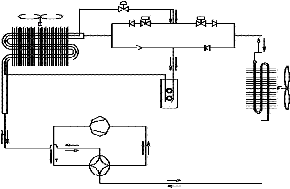
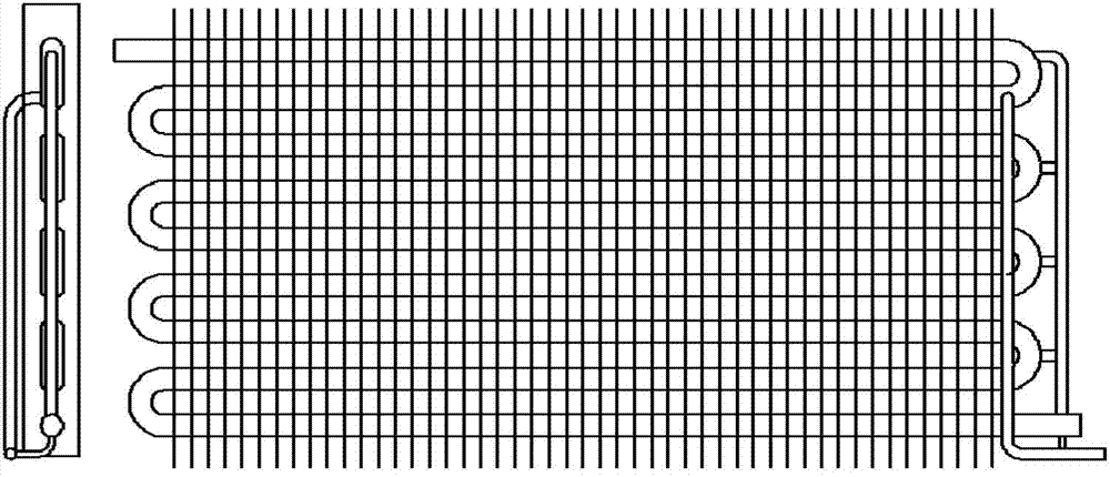
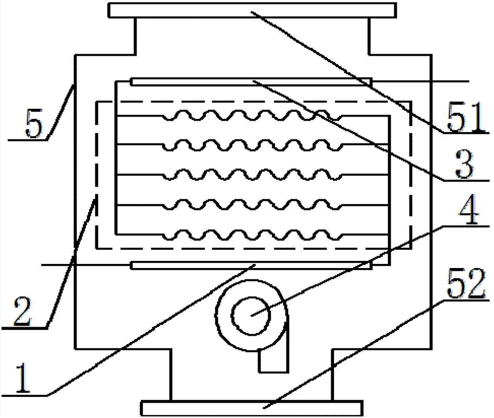
[0031] Embodiment 1 of the present invention is the first type of multi-branch outdoor heat exchanger for synchronous heat exchange. The fan 4 of the multi-branch indoor heat exchanger for synchronous heat exchange is the upper air outlet, and its wind speed distribution vector diagram conforms to the upper triangle. When the structure of the heat exchanger is determined, this specific air supply mode has a one-to-one correspondence with the upper triangle distribution vector diagram of the wind speed. It can be seen from the upper triangle wind speed distribution vector diagram that the upper part of the heat exchanger has a higher wind speed, so when the external air sweeps across the upper branch of the heat exchanger, the effect of forced heat exchange with the refrigerant in the tube is good, so the present invention makes the uppermost part of the indoor heat exchanger One of the branches is set as subcooling coil 1; the wind speed at the lower part of the heat exchanger...


PUM


Abstract

The invention discloses a multi-branch indoor heat exchanger for synchronous heat exchange. The multi-branch indoor heat exchanger comprises a super cooling coil, a multi-branch heat exchange coil, an over-heating coil and a fan, wherein the super cooling coil and the over-heating coil are arranged at the positions with the best heat exchange effect and the poorest heat exchange effect in the indoor heat exchanger respectively and are parallel to the multi-branch heat exchange coil; a refrigeration outlet of the super cooling coil is connected with a refrigeration inlet of the multi-branch heat exchange coil; and a refrigeration outlet of the multi-branch heat exchange coil is connected with a refrigeration inlet of the over-heating coil. The equipment provided by the invention is suitable for various types of air conditioning systems; the stability and the reliability for working of an expansion valve can be effectively enhanced; a compressor is prevented from performing wet compression; and the efficiency of the system and the safety and the reliability for operation are effectively improved.

Description

technical field [0001] The invention belongs to the technical field of building environment and equipment engineering, and relates to a multi-branch indoor heat exchanger, in particular to a synchronous heat exchange multi-branch indoor heat exchanger. Background technique [0002] The multi-branch indoor heat exchanger is a kind of partition wall heat exchanger that makes the refrigerant fluid and the indoor air fluid undergo forced heat exchange, thereby improving the indoor environment. It can be used as a room heater, room cooler or air purifier for cooling / heating or purifying indoor air to provide people with a comfortable indoor environment. In the cooling condition, the multi-branch indoor heat exchanger is an evaporator, which transfers part of the heat of the air to the refrigerant to reduce the indoor temperature; Part of the heat of the agent is transferred to the air, increasing the indoor temperature. [0003] At present, most of the indoor heat exchangers do...

Claims


Application Information

Patent Timeline
Patent Type & Authority Patents(China)
IPC IPC(8): F25B39/00
Inventor 张忠斌黄虎袁祎刘晓露张敬坤刘娜潘亚梅
Owner NANJING NORMAL UNIVERSITY
Why Eureka
Try Eureka