Efficient full-wet inner surface evaporator

An evaporator and inner surface technology, applied in evaporators/condensers, compressors, refrigeration components, etc., can solve problems such as poor oil return effect of compressors, low heat exchange efficiency, cylinder flushing accidents, etc., to ensure normal operation Safe operation, improve heat transfer efficiency, and avoid segmental flow effects

Inactive Publication Date: 2012-01-18
SOUTHEAST UNIV
View PDF0 Cites 0 Cited by
  • Summary
  • Abstract
  • Description
  • Claims
  • Application Information

AI Technical Summary

Problems solved by technology

[0002] The existing evaporator has the following deficiencies: first, the heat exchange tubes of the existing evaporator are horizontal, the refrigerant gas and liquid flow in sections, and the heat exchange efficiency is low
Second, the refrigerant is directly sent to the compressor or the gas-liquid separator after being evaporated by the evaporator. Due to the hysteresis and periodic oscillation instability of the traditional refrigeration throttle valve adjustment, the refrigerant flowing out of the evaporator will inevitably bring A certain amount of liquid refrigerant is produced. According to the experimental research of Dutch scholars, even if the superheat of the refrigerant outlet is 5°C, there is still a certain amount of liquid refrigerant in the refrigerant vapor.
If the compressor sucks wet steam, wet compression will occur during the compression process, and wet compression will cause various adverse consequences. In severe cases, liquid shock, cylinder flushing accidents, and even damage to the compressor will occur. It is strictly forbidden to occur during actual operation.
Third, the oil return effect of the compressor of the existing evaporator is not good

Method used


Image

  • Efficient full-wet inner surface evaporator
  • Efficient full-wet inner surface evaporator
  • Efficient full-wet inner surface evaporator

Examples


Embodiment Construction

[0011] The following describes the technical solution of the present invention in detail through a best embodiment in conjunction with the accompanying drawings, but the protection scope of the present invention is not limited to the embodiment.

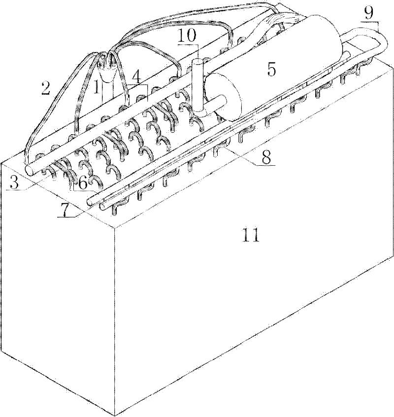
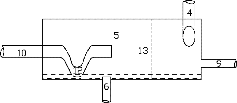
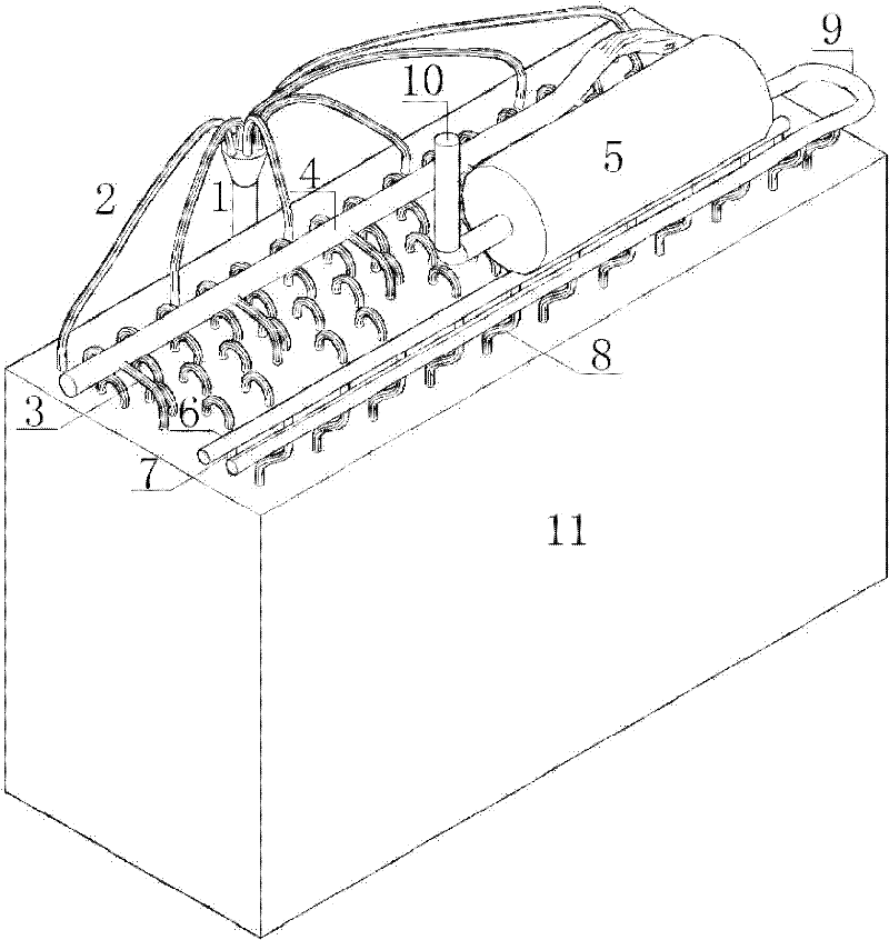
[0012] A high-efficiency full-humidity internal surface evaporator, mainly composed of a refrigerant distributor 1, a primary evaporation heat exchange tube 2, a refrigerant primary return pipe 3, a refrigerant primary return main pipe 4, a gas-liquid separator (5) and a refrigerant The air return pipe 10 is connected in sequence, and the bottom of the gas-liquid separator 5 is connected to the secondary evaporation air intake main pipe 6, the secondary evaporation heat exchange pipe 7, the refrigerant secondary return air pipe 8 and the secondary evaporation return air main pipe 9 , and finally return to the gas-liquid separator 5; the primary evaporation heat exchange tube 2 and the secondary evaporation heat exchange tube 7 are dis...


PUM


Abstract

The invention discloses an efficient full-wet inner surface evaporator which is mainly formed by connecting a refrigerant distributor, a first evaporating heat exchange pipe, a first refrigerant air return pipe, a first refrigerant air return main pipe, a gas-liquid separator and a refrigerant air return pipe in sequence. The evaporator also comprises a secondary evaporating heat exchange assembly, wherein the secondary evaporating heat exchange assembly is formed by connecting a secondary evaporating air inlet main pipe, a secondary evaporating heat exchange pipe, a secondary refrigerant airreturn pipe and a secondary evaporating air return main pipe; and a refrigerant entering the gas-liquid separator enters the secondary evaporating heat exchange pipe for carrying out secondary evaporation by the secondary evaporating air inlet main pipe and returns into the gas-liquid separator by syphonage. The invention has certain ingenuity on improving the heat exchange efficiency of the evaporator and solving the problems of wet compression and oil return, can improve the heat transfer performance of the evaporator and improve the performance coefficient of a unit by 15 percent or so, isnot only suitable for a pure medium but also suitable for a mixed medium.

Description

technical field [0001] The invention belongs to the refrigeration field, and in particular relates to a high-efficiency full-humidity inner surface evaporator, which is applicable to all tube-fin evaporators. Background technique [0002] The existing evaporator has the following deficiencies: first, the heat exchange tubes of the existing evaporator are horizontal, the refrigerant gas and liquid flow in stages, and the heat exchange efficiency is low. Second, the refrigerant is directly sent to the compressor or the gas-liquid separator after being evaporated by the evaporator. Due to the hysteresis and periodic oscillation instability of the traditional refrigeration throttle valve adjustment, the refrigerant flowing out of the evaporator will inevitably bring A certain amount of liquid refrigerant is produced. According to the experimental research of Dutch scholars, even if the superheat of the refrigerant outlet is 5°C, there is still a certain amount of liquid refriger...

Claims


Application Information

Patent Timeline
Patent Type & Authority Patents(China)
IPC IPC(8): F25B31/00F25B39/02F25B43/00
Inventor 陈九法乔卫来安二铭朱晟徐相梅陈军伟高龙庞丽颖
Owner SOUTHEAST UNIV
Why Eureka
Try Eureka