Electromagnetic lock working state detecting method

A technology of working state and detection method, applied in the direction of measuring electricity, measuring device, measuring electrical variable, etc., can solve the problem that it is difficult to obtain the working state of the electromagnetic lock, it is impossible to judge the reliable opening or locking of the friction plate type electromagnetic lock, and the performance is degraded. question

Active Publication Date: 2019-02-22
BEIJING RES INST OF PRECISE MECHATRONICS CONTROLS
View PDF11 Cites 4 Cited by
  • Summary
  • Abstract
  • Description
  • Claims
  • Application Information

AI Technical Summary

Problems solved by technology

Among them, the friction plate electromagnetic lock can continue to work when the electromagnetic lock cannot be opened normally, but its performance is reduced. Therefore, the application of the friction plate electromagnetic lock in missile weapons with high reliability requirements more
[0003] Due to the small stroke of the friction plate electromagnetic lock, which is usually less than 1mm, compared with the bolt type electromagnetic lock, it is difficult for the friction plate electromagnetic lock to directly obtain the working status of the electromagnetic lock through the position sensor, that is, the sensor cannot judge until it passes Whether the friction plate electromagnetic lock is reliably opened or locked

Method used


Image

  • Electromagnetic lock working state detecting method
  • Electromagnetic lock working state detecting method
  • Electromagnetic lock working state detecting method

Examples


Embodiment 1

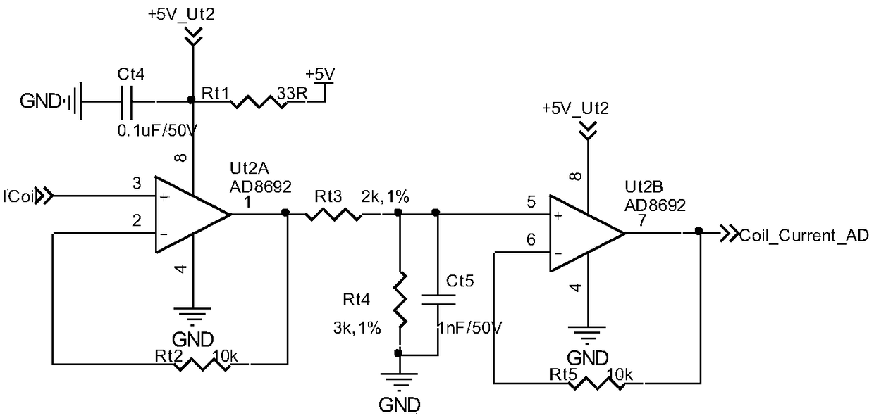
[0035] Embodiment 1: The hardware detection is an electromagnetic lock coil operating current detection circuit based on Hall detection, including a coil current detection circuit in the electromagnetic lock and a coil current signal conditioning circuit in the electromagnetic lock, specifically:

[0036] see figure 1 , the coil current detection circuit in the electromagnetic lock includes: an electromagnetic lock power supply module, an electromagnetic lock coil, and a current sensor, wherein the output end of the electromagnetic lock power supply module is connected to the input end of the electromagnetic lock coil, and the output end of the electromagnetic lock coil is connected to the current sensor , the output terminal of the electromagnetic lock power supply module is also connected to the current sensor, and the current sensor outputs the current detection value of the electromagnetic lock. Wherein, the current sensor is the GO 10-SME current sensor of LEM Company. Wh...

Embodiment 2

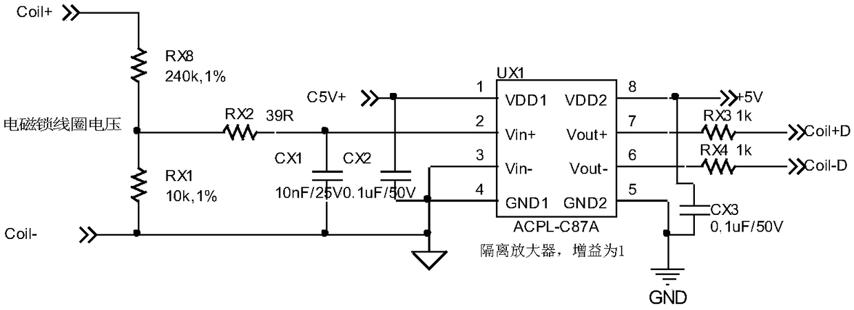
[0038] Embodiment 2: The hardware detection is an isolated electromagnetic lock coil operating voltage detection circuit based on voltage optical isolation acquisition, including a voltage isolation acquisition circuit, an instrument amplifier circuit, and an isolated power supply circuit. specific:

[0039] see image 3 , The voltage isolation acquisition circuit isolates the electromagnetic lock power supply circuit as the primary side from the electromagnetic lock power supply voltage acquisition circuit as the secondary side, and the ratio of the input voltage of the primary side to the output voltage of the secondary side is 1. The voltage isolation acquisition circuit includes an optical isolation amplifier, which includes a sigma-delta AD converter, an optocoupler and a sigma-delta DA converter, and the optical isolation amplifier converts the primary side input analog signal into a digital signal It is transmitted to the secondary side through the optocoupler to achie...


PUM


Abstract

The invention relates to an electromagnetic lock working state detecting method. The method comprises steps of hardware detection and software parameter identification. Parameters include a rotor position theta of a motor and a torque current Iq of the motor. The hardware detection is based on a Hall-detection-based electromagnetic lock coil operation current detection circuit or an isolated electromagnetic lock coil working voltage detecting circuit based on voltage optical isolation collection.

Description

technical field [0001] The invention relates to a method for detecting the working state of an electromagnetic lock. The electromagnetic lock is used in the fields of missile weapons, aviation, electric vehicles and industrial robots. The target of the working state detection is reliable opening or reliable locking. Background technique [0002] In missile weapons equipped with air rudders, in order to ensure that the rudder surface of the air rudder will not deflect during the flying stage or the transportation stage, an electromagnetic lock is usually added to one end of the motor shaft of the servo actuator, and the motor shaft is locked by the electromagnetic lock. To achieve the purpose of locking the output of the actuator. Commonly used electromagnetic locks are divided into two types: friction plate type or latch type. Among them, the friction plate electromagnetic lock can continue to work when the electromagnetic lock cannot be opened normally, but its performance...

Claims


Application Information

Patent Timeline
Patent Type & Authority Applications(China)
IPC IPC(8): G01R31/00G01R19/00
CPCG01R19/00G01R31/00
Inventor 陈鹏姜玉峰高健张成浩于丹焦震
Owner BEIJING RES INST OF PRECISE MECHATRONICS CONTROLS
Why Eureka
Try Eureka