Transformer continuous coil spiral transposition structure and manufacturing method thereof

A technology of transformers and coils, applied in coil manufacturing, transformer/inductor coils/windings/connections, transformer/inductor components, etc., can solve problems such as increased load loss, increased coil temperature rise, and accelerated insulation aging speed. , to achieve the effect of reducing the temperature rise of the coil, reducing the circulating current loss, and reducing the circulating current

Pending Publication Date: 2019-02-22
FUZHOU TIANYU ELECTRIC
View PDF0 Cites 7 Cited by
  • Summary
  • Abstract
  • Description
  • Claims
  • Application Information

AI Technical Summary

Problems solved by technology

The traditional coil transposition method is not effective in reducing the circulating current between the wires. The circulating current loss sometimes reaches more than 10% of the

Method used


Image

  • Transformer continuous coil spiral transposition structure and manufacturing method thereof
  • Transformer continuous coil spiral transposition structure and manufacturing method thereof
  • Transformer continuous coil spiral transposition structure and manufacturing method thereof

Examples


Embodiment 1

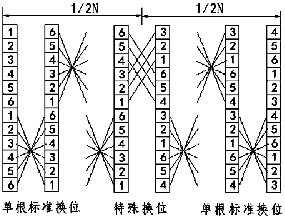
[0015] Embodiment 1: as figure 1 As shown, a transformer continuous coil-like spiral transposition structure includes multi-layer wire cake groups arranged along the coil axis, and each layer of wire cake groups is wound by six wires stacked in the width direction. At least 2 turns of six overlapping wires are wound; a special transposition structure is adopted between two adjacent wire cake groups at half of the coil axis, and a standard transposition structure is adopted between the other two adjacent layers of wire cake groups ; In the special transposition structure, the wires are divided into two groups, that is, a group of three. When transposing, the 3 wires in the upper group and the 3 wires in the bottom group are exchanged for the overall position.

[0016] In this embodiment, the standard transposition structure adopts a single standard transposition structure, and all the wires in the single standard transposition structure are arranged in reverse order when they a...

Embodiment 2

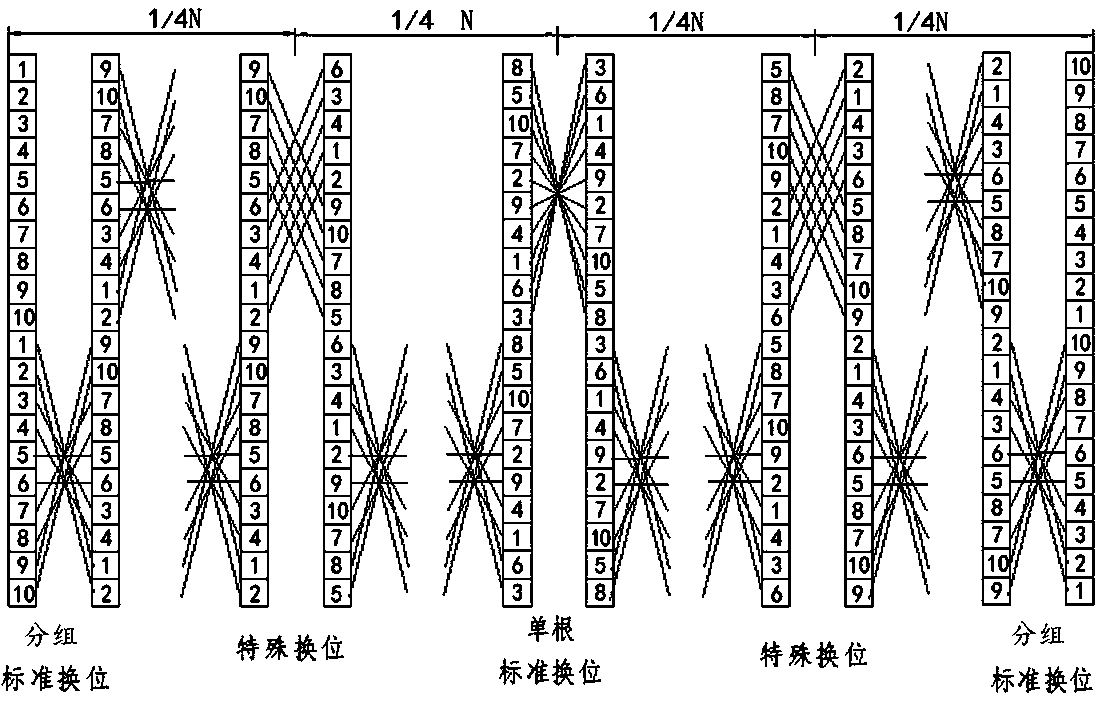
[0019] Embodiment 2: as figure 2 As shown, the number of wires is 10, and a special transposition structure is adopted between the two layers of adjacent wire cake groups at the quarter and three quarters of the coil axis. In the special transposition structure, the conductors are divided into Two groups, that is, a group of five. When transposition, the 5 conductors of the upper group and the 5 conductors of the bottom group are exchanged for the overall position; the other two adjacent layers of wire cake groups adopt a standard transposition structure.

[0020] In this embodiment, the standard transposition structure includes a single standard transposition structure and a grouped standard transposition structure; a single standard transposition structure is adopted between two adjacent wire cake groups at half of the coil axis, The grouping standard transposition structure is adopted between the remaining two adjacent layers of wire cake groups; all conductors in a single...


PUM


Abstract

The invention relates to a transformer continuous coil spiral transposition structure, a transposition method thereof and a manufacturing method thereof. The transformer continuous coil spiral transposition structure comprises a plurality of layers of wire cake groups which are axially arranged along a coil, wherein each layer of the wire cake group is formed by winding a plurality of wires whichare overlapped in the width direction; a special transposition structure is adopted between two adjacent layers of the wire cake groups at one half of the axial direction of the coil, or the special transposition structure is adopted between two adjacent layers of the wire cake groups at one quarter and three quarters of the axial direction of the coil, and a standard transposition structure is adopted between the other two adjacent layers of the wire cake groups; in the special transposition structure, the wires are divided into two groups, and the upper group of wires and the lower group ofwires are subjected to integral position exchange during transposition. According to the transformer continuous coil spiral transposition structure, the basic consistency of the resistance of each wire is ensured, the potential differences between the wires are greatly reduced, the circulating current is greatly reduced, the circulation loss is greatly reduced, the load loss during the operation of the transformer is further reduced, the temperature rise of the coil is reduced, and the service life of the insulating material is prolonged.

Description

technical field [0001] The invention relates to a transformer continuous coil-like spiral transposition structure and a manufacturing method thereof. Background technique [0002] Continuous coils are the most common coils in power transformers, consisting of many positive and negative coils connected in series along the axial direction. According to the size of the current passing through the coil, the coil can be wound in parallel by single or multiple paper-wrapped flat wires, and the number of parallel wires can reach up to 12. When winding a coil with parallel wires, the wire on the outer diameter side is longer than the inner diameter side, so the resistance of each wire is different, and the leakage magnetic field distribution of the coil is triangular. The wire near the main magnetic leakage channel is in a position with high leakage flux density, so the induced leakage potential is larger than that induced by the wire far away from the main channel, so there is a p...

Claims


Application Information

Patent Timeline
IPC IPC(8): H01F27/28H01F27/34H01F41/06
CPCH01F27/2823H01F27/2876H01F27/34H01F41/06H01F2027/2838
Inventor 张长庚叶红恩陈伯根
Owner FUZHOU TIANYU ELECTRIC
Why Eureka
Try Eureka