Chip arrangement machine used for chip packaging

A technology of chip encapsulation and arranging machine, which is applied in the direction of conveyor objects, transportation and packaging, electrical components, etc. It can solve the problems of chip damage and low manual operation efficiency, and achieve the effects of reducing production costs, preventing oil stains, and preventing damage

Pending Publication Date: 2019-02-22
KUNSHAN YINAITE PRECISION MOLD
View PDF13 Cites 6 Cited by
  • Summary
  • Abstract
  • Description
  • Claims
  • Application Information

AI Technical Summary

Problems solved by technology

[0003] From chip production to final molding, in order to improve efficiency, various companies carry out division of labor and cooperation. Some companies are only responsible for the production of chips, while some companies are only responsible for packaging. Therefore, in the process of transportation, the chips are transported from the chip manufacturer to the chip packager. Mobile, chip boxes are usually used to load chips during transportation, and in order to ensure that adjacent chips will not be damaged due to collisions, multiple placement bars for placing chips are set in the chip box. Arranging multiple chips in the vertical direction can save space and improve transportation efficiency; when packaging chips, it is necessary to take out the chips one by one from the chip box and put them into the corresponding mold. This operation usually uses It is realized manually. Sometimes too much force may cause damage to the chip. Sometimes it will be stained with oil and affect the use of the chip. The efficiency of manual operation is low.

Method used


Image

  • Chip arrangement machine used for chip packaging
  • Chip arrangement machine used for chip packaging
  • Chip arrangement machine used for chip packaging

Examples


Embodiment Construction

[0040] The present invention will be described in detail below in conjunction with the accompanying drawings.

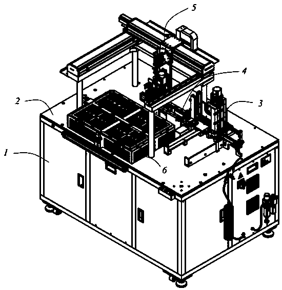
[0041] Such as figure 1 A chip packaging machine is shown, which includes a frame 1 and a workbench 2 located on the frame 1. An automatic feeding unit 3 is set on the workbench 2 for automatic grabbing of chips 7. Unit 5, stacking unit 6, and the control unit that controls the action of the chip unloading machine, the delivery of the chip 7 is realized through the delivery unit 4 between the automatic feeding unit 3 and the automatic grabbing unit 5, and the chip box 8 is placed on the automatic feeding unit 3 Inside, the automatic feeding unit 3 automatically transports a single chip 7 to the conveying unit 4, and the automatic grabbing unit 5 grabs a single chip 7 and places it in the stacking unit 6. The above actions are all driven by the control unit, which realizes the automation of chip arrangement and improves the efficiency of chip arrangement .

[0042] ...


PUM


Abstract

The invention discloses a chip arrangement machine used for chip packaging. The machine includes a machine rack and a work bench. The work bench is provided with an automatic feeding unit, an automatic gripping unit, a stacking unit and a control unit; chip conveying is achieved between the automatic feeding unit and the automatic gripping unit through a conveying unit; a chip box is placed in theautomatic feeding unit, the automatic feeding unit automatically transport individual chips to the conveying unit, the automatic gripping unit grabs the individual chips and places the chips on thestacking unit, and a whole action is controlled by the control unit. Automation of chip removal and placement is achieved, workers are not utilized any longer, thus eliminating the problem of chip damage and oil stains contamination, the damage rate of the chip during a sub-packaging process is reduced, the production efficiency is reduced, and the production cost is reduced.

Description

technical field [0001] The invention relates to an automatic equipment in the technical field of packaging, in particular to a chip packaging machine for chip packaging. Background technique [0002] Packaging is the process of assembling integrated circuits into chip final products. Simply put, it is to put the produced integrated circuit die on a substrate that acts as a load bearing, lead out the pins, and then fix and package them as a whole. [0003] From chip production to final molding, in order to improve efficiency, various companies carry out division of labor and cooperation. Some companies are only responsible for the production of chips, while some companies are only responsible for packaging. Therefore, in the process of transportation, the chips are transported from the chip manufacturer to the chip packager. Mobile, chip boxes are usually used to load chips during transportation, and in order to ensure that adjacent chips will not be damaged due to collisions...

Claims


Application Information

Patent Timeline
Patent Type & Authority Applications(China)
IPC IPC(8): H01L21/67H01L21/677
CPCH01L21/67271H01L21/67706
Inventor 钟旭光夏广清杨治兵江爱民平卫涛
Owner KUNSHAN YINAITE PRECISION MOLD
Why Eureka
Try Eureka