
Card support popup mechanism and mobile terminal

A mobile terminal and ejection mechanism technology, which is applied in the direction of telephone structure, telephone communication, electrical components, etc., can solve the problems of increased processing cost, inconvenient use, easy blocking of thimble holes, etc., and achieves high feasibility and reduces punching procedures. , the effect of reducing costs

Pending Publication Date: 2019-02-22
SHANGHAI MORUAN COMM TECH
View PDF6 Cites 4 Cited by
  • Summary
  • Abstract
  • Description
  • Claims
  • Application Information

AI Technical Summary

Problems solved by technology

In this way, the card tray is pushed out of the card slot, and the thimble needs to be prepared at any time. Once the card tray needs to be pushed out, but there is no thimble around, it will not be able to meet the needs of pushing out the card tray, and it is more inconvenient to use.
In addition, ejector pin holes need to be punched on the shell surface of the mobile terminal, and the ejector pin holes are exposed to the outside. After some small impurities enter the ejector pin holes, it is easy to block the ejector pin holes, causing the ejector pins to be unable to enter, and the card holder is pushed out, causing the mobile terminal The card tray cannot be pushed out from the card slot
In addition, each shell must be processed with thimble holes, which also increases the processing cost

Method used


Image

  • Card support popup mechanism and mobile terminal
  • Card support popup mechanism and mobile terminal
  • Card support popup mechanism and mobile terminal

Examples


Embodiment Construction

[0033] In order to make the purpose, technical solutions and advantages of the embodiments of the present invention more clear, various implementation modes of the present invention will be described in detail below in conjunction with the accompanying drawings. However, those of ordinary skill in the art can understand that, in each implementation manner of the present invention, many technical details are provided for readers to better understand the present application. However, even without these technical details and various changes and modifications based on the following implementation modes, the technical solution claimed in this application can also be realized.

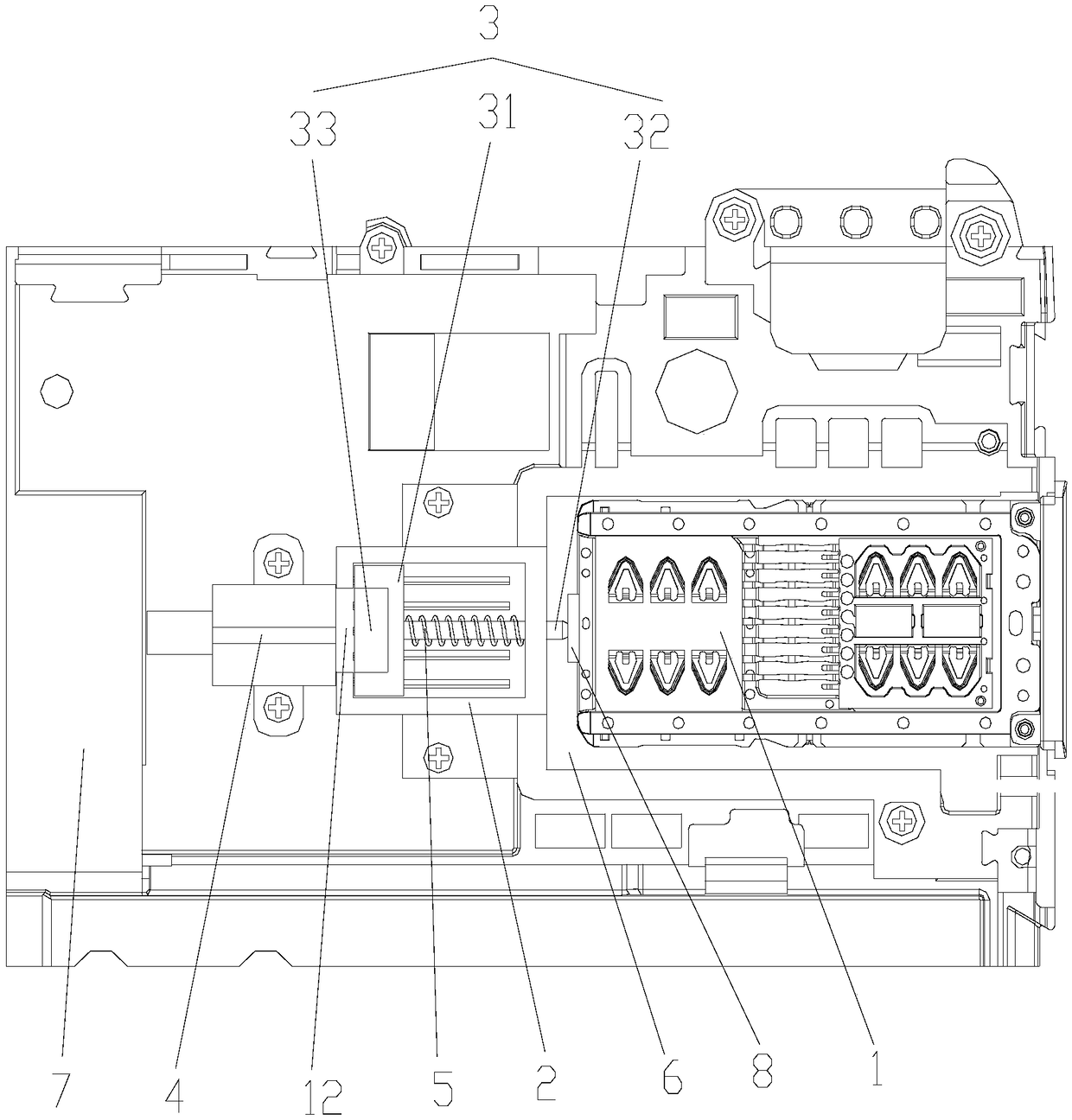
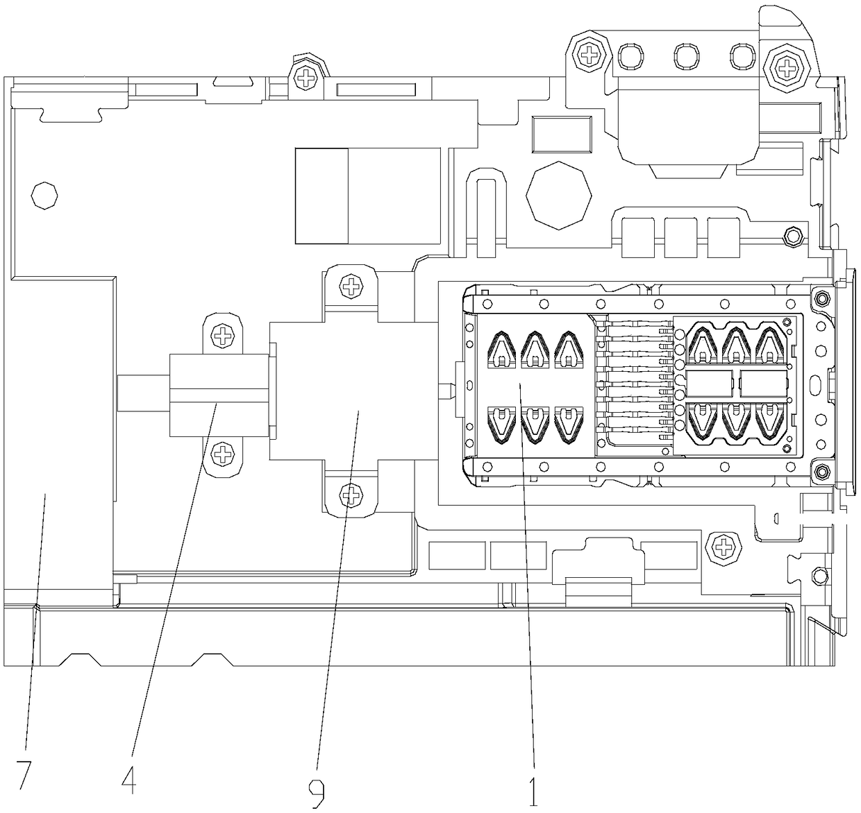
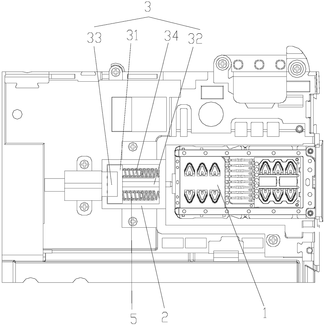
[0034] The first embodiment of the present invention relates to an embodiment of the present invention provides a card tray ejection mechanism, such as figure 1 As shown, it is set in the casing of the mobile terminal, and the card tray 1 is pushed out of the card slot 6 of the mobile terminal. The card tra...


PUM


Abstract

The embodiment of the invention relates to the field of terminal devices and discloses a card support popup mechanism and a mobile terminal, wherein the card support popup mechanism pushes a card support out of a card slot of the mobile terminal; the card support popup mechanism comprises a limiting frame, a thimble component, an electromagnet, and a resilient part. The limiting frame is arrangedopposite to the card slot; the thimble component is slidably arranged in the limiting frame along a push direction of the card support; the electromagnet is arranged opposite to one side of the thimble component far away from the card slot and is electrically connected with a main board of the mobile terminal; the main board supplies power for the electromagnet; after being electrified, the electromagnet generates a magnetic field; one side of the thimble component opposite to the electromagnet is a magnetic side of a repelling magnetic field; the resilient part is arranged in the limiting frame along the sliding direction of the thimble component; one end of the resilient part is abutted against the thimble component and the other end thereof is abutted against the limiting frame. Compared with the prior art, the scheme is applied so that the card support is pushed out from the card slot more conveniently, safely and reliably, thereby reducing the punching process and reducing the cost.

Description

technical field [0001] The embodiment of the present invention relates to the field of terminal equipment, in particular to a card tray ejecting mechanism and a mobile terminal. Background technique [0002] At present, electronic terminals such as mobile phones in the market use flat push card holders, and a card slot is provided on the mobile terminal, and the card holder is placed in the card slot. A thimble hole is provided beside the card slot of the housing, and when the card holder needs to be pushed out of the card slot, a thimble is poked into the thimble hole to push the card holder out of the card slot. In this way, the card tray is pushed out of the card slot, and the thimble needs to be prepared at any time. Once the card tray needs to be pushed out, but there is no thimble around, it will not be able to meet the needs of pushing out the card tray, which is inconvenient to use. And the surface of the mobile terminal shell needs to be punched with thimble holes,...

Claims


Application Information

Patent Timeline
Patent Type & Authority Applications(China)
IPC IPC(8): H04M1/02H04B1/3818
CPCH04B1/3818H04M1/026
Inventor 李化顺张亮
Owner SHANGHAI MORUAN COMM TECH
Learn More