Air conditioner
一种空调装置、调节装置的技术,应用在空调系统、空间供热和通风、用空气流作屏蔽等方向,能够解决除湿不充分、加热量不足等问题,达到避免除湿不充分、降低能耗、提高能耗比的效果
- Summary
- Abstract
- Description
- Claims
- Application Information
AI Technical Summary
Problems solved by technology
Method used
Image

Examples
Embodiment approach 1
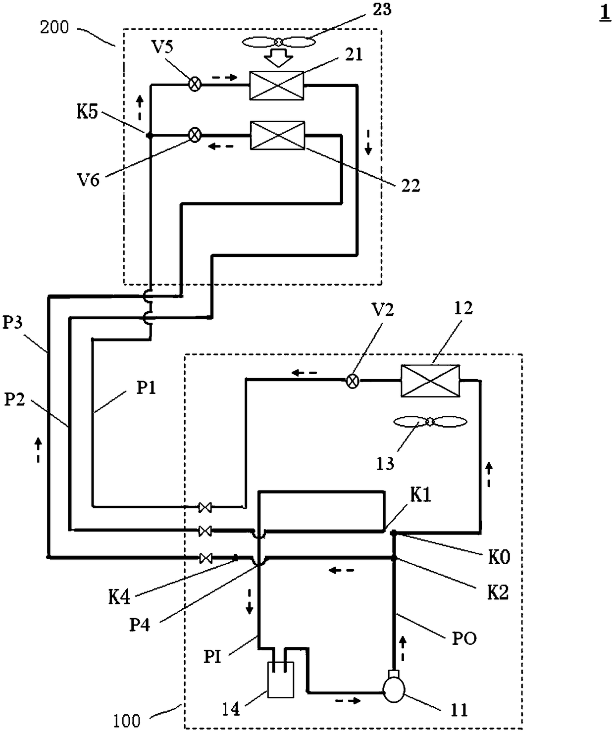
[0062] First, refer to figure 1 The basic configuration of the air conditioner 1 according to Embodiment 1 will be described.
[0063] like figure 1 As shown, the air conditioner 1 of this embodiment includes an outdoor unit 100 and a dehumidifying and reheating indoor unit 200, wherein the outdoor unit 100 has: a compressor 11 as a compression mechanism, an outdoor heat exchanger 12, an outdoor fan 13, and The valve V2 of the outdoor-side refrigerant regulating device, the liquid storage tank 14 as a liquid storage device, and the dehumidification-reheating indoor unit 200 has a dehumidification heat exchanger 21 as a first indoor heat exchanger and a dehumidification heat exchanger 21 as a first indoor refrigerant Regulator valve V5. Here, an electric valve or a solenoid valve can be used for the valve V5.
[0064] Additionally, if figure 1 As shown, the air conditioner 1 of this embodiment uses the first piping group to connect the discharge side of the compressor 11...
Embodiment approach 2
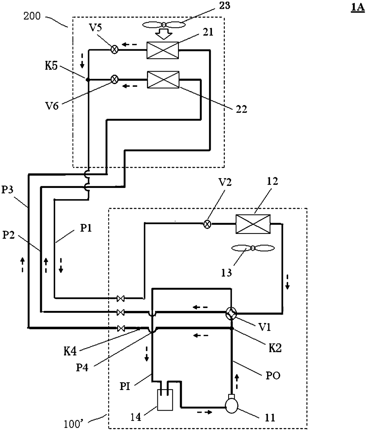
[0077] figure 2 It is a schematic diagram which shows the circuit structure of 1 A of air-conditioning apparatuses concerning Embodiment 2 of this invention. The air conditioner 1A of the present embodiment is basically the same in structure as the air conditioner 1 of the above-mentioned first embodiment, and here, the same symbols as those of the above-mentioned first embodiment are assigned the same symbols, and the differences from the above-mentioned first embodiment are designated by the same reference numerals. The center is described.
[0078] In this embodiment, if figure 2 As shown, the outdoor unit 100' includes a four-way switching valve V1 as a first switching device. Switching between a switching state and a second switching state in which the four-way switching valve V1 communicates the first pipe P1 with the suction pipe PI and connects the second pipe P2 with the discharge pipe PO, in which In the second switching state, the four-way switching valve V1 co...
Embodiment approach 3
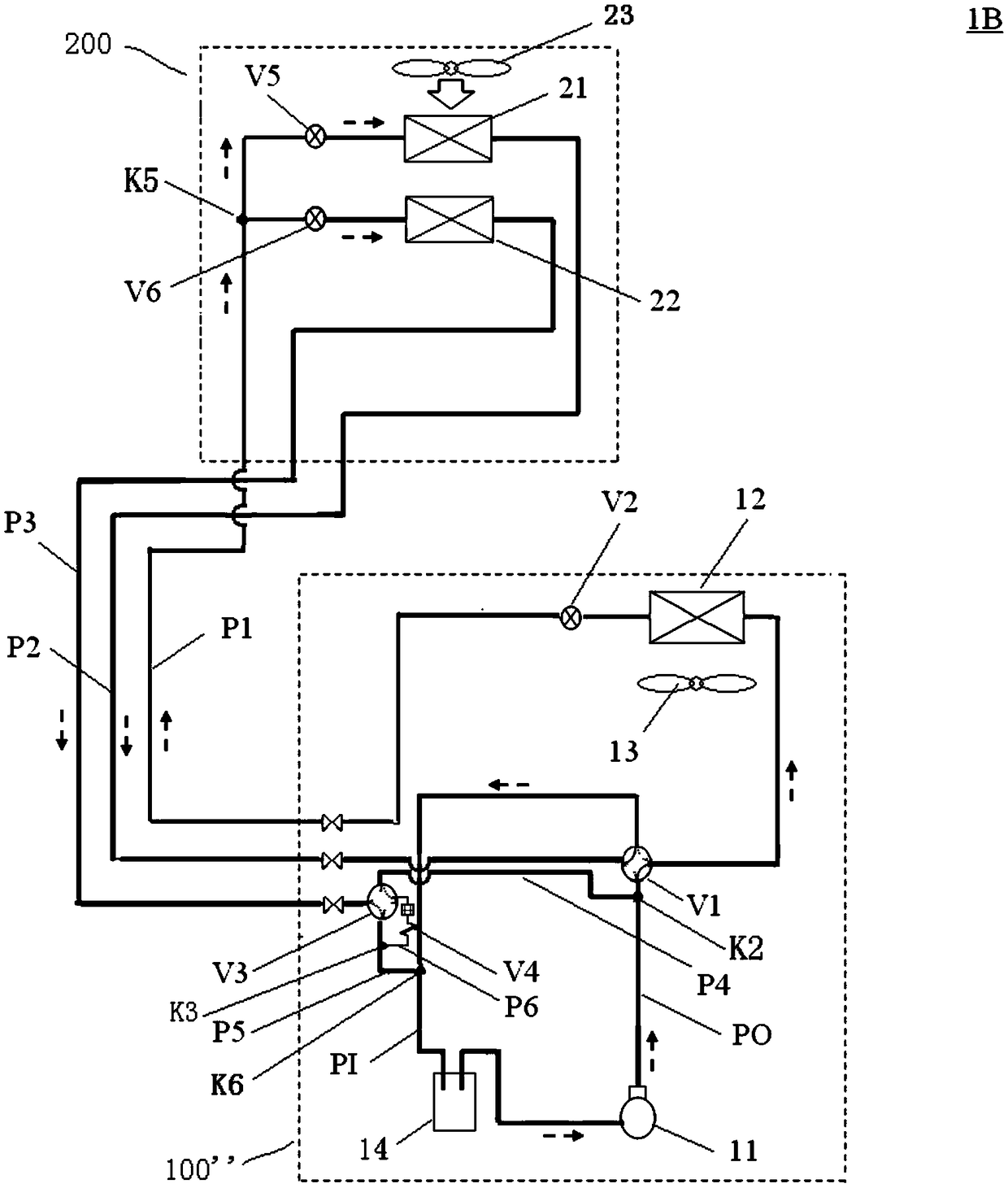
[0089] image 3 It is a schematic diagram which shows the circuit structure of the air-conditioning apparatus 1B which concerns on Embodiment 3 of this invention. The air conditioner 1B of this embodiment is basically the same in structure as the air conditioner 1A of the above-mentioned second embodiment, and here, the same symbols as those of the above-mentioned second embodiment are attached with the same symbols, and the differences from the above-mentioned second embodiment are assigned. The center is described.
[0090] In this embodiment, if image 3 As shown, the outdoor unit 100" of the air conditioner 1B includes a branch pipe P5, a branch pipe P6, a throttling device V4, and a four-way switching valve V3 as a second switching device. Here, the branch pipe P5 starts from the suction Tube PI image 3 In the point K6 branch out, the branch pipe P6 is from the branch pipe P5 image 3 The point K3 is branched out, the throttling device V4 is arranged on the branch pi...
PUM
 Abstract
Description
Claims
Application Information
 - R&D
- Intellectual Property
- Life Sciences
- Materials
- Tech Scout
- Unparalleled Data Quality
- Higher Quality Content
- 60% Fewer Hallucinations
Browse by: Latest US Patents, China's latest patents, Technical Efficacy Thesaurus, Application Domain, Technology Topic, Popular Technical Reports.
© 2025 PatSnap. All rights reserved.Legal|Privacy policy|Modern Slavery Act Transparency Statement|Sitemap|About US| Contact US: help@patsnap.com