Check patentability & draft patents in minutes with Patsnap Eureka AI!

System and method for calibration of voltage-controlled oscillator in phase-lock loop

A voltage-controlled oscillator, phase-locked loop technology, applied in the direction of automatic power control, electrical components, etc., can solve the problems of long calibration time of the voltage-controlled oscillator, achieve faster phase convergence speed, shorten phase detection time limit, improve Effect of Phase Lock Speed

Pending Publication Date: 2019-02-26
SHANGHAI HUAHONG ZEALCORE ELECTRONICS TECH CO LTD
View PDF4 Cites 2 Cited by
  • Summary
  • Abstract
  • Description
  • Claims
  • Application Information

AI Technical Summary

Problems solved by technology

[0007] The technology to be solved by the present invention is a calibration system and method of a voltage-controlled oscillator in a phase-locked loop to solve the defect that the calibration time of the voltage-controlled oscillator is long

Method used


Image

  • System and method for calibration of voltage-controlled oscillator in phase-lock loop
  • System and method for calibration of voltage-controlled oscillator in phase-lock loop
  • System and method for calibration of voltage-controlled oscillator in phase-lock loop

Examples


Embodiment 1

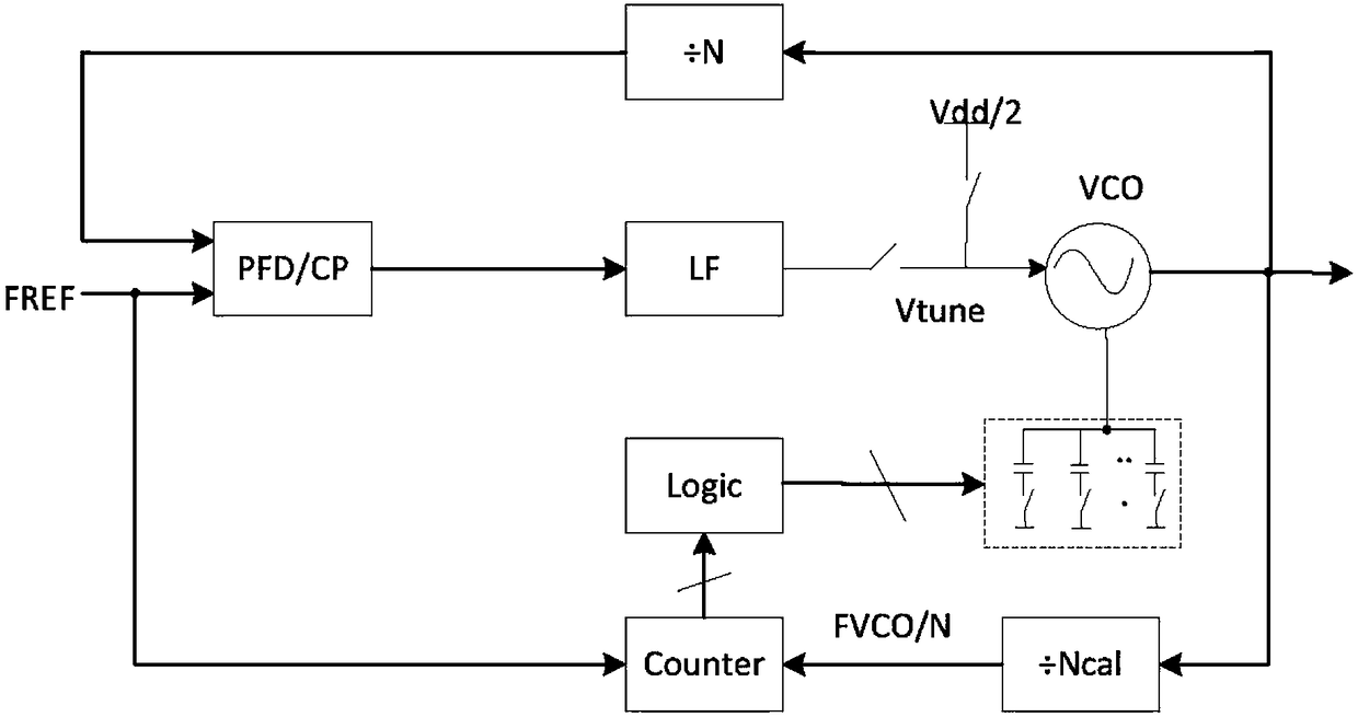
[0044] image 3 The schematic structural diagram of the calibration system of the voltage-controlled oscillator in the phase-locked loop provided by Embodiment 1 of the present invention, this embodiment can be applied to the adjustment of the voltage-controlled signal of the voltage-controlled oscillator 2 during the convergence of the phase-locked loop , to calibrate the phase tracking of the phase locked loop, the calibration system includes: a gain regulation unit 11 and a calibration detection unit 12 .

[0045] The gain regulation unit 11 is connected to the input terminal of the voltage-controlled oscillator 2, and is used to instruct the voltage-controlled oscillator 2 to output a voltage-controlled signal of the first loop bandwidth before the phase tracked by the phase-locked loop is stable. .

[0046] Optionally, the gain regulation unit 11 supplies current to the voltage-controlled oscillator 2 with a larger gain after the voltage-controlled oscillator 2 is powere...

Embodiment 2

[0087] Such as Figure 8 As shown, the second embodiment provides a method for calibrating a voltage-controlled oscillator in a phase-locked loop. The calibration method may be executed based on the calibration system designed in any optional solution in the above embodiments. It can also be performed by other calibration systems following the steps below.

[0088] Step S110 , before the phase tracked by the phase-locked loop stabilizes, instruct the voltage-controlled oscillator to output a voltage-controlled signal with a first loop bandwidth, and collect the voltage of the voltage-controlled oscillator.

[0089] Optionally, after the voltage-controlled oscillator is powered on, a current is provided to the voltage-controlled oscillator with a larger gain, so that the voltage-controlled signal output by the voltage-controlled oscillator has a larger loop bandwidth. After the voltage-controlled oscillator is calibrated to determine that the phase tracking is stable, the loo...


PUM


Abstract

The present invention discloses a system and a method for calibration of a voltage-controlled oscillator in a phase-lock loop. The system comprises: a gain regulation and control unit connected with an input end of a voltage-controlled oscillator and configured to indicate the voltage-controlled oscillator to output voltage controlled signals with a first loop bandwidth prior to stabilization of the phases tracked by the phase-lock loop; a calibration detection unit connected with the voltage-controlled oscillator and configured to collect a voltage in the voltage-controlled oscillator, perform calibration of the loop bandwidth of the voltage controlled signals based on a comparison result of the collected voltage and a preset detection voltage window and indicate the gain regulation and control unit to reduce the first loop bandwidth to the second loop bandwidth when it is determination that the phases are stable tracked by the voltage-controlled oscillator.

Description

technical field [0001] The invention relates to electronic circuit technology, in particular to a calibration system and method for a voltage-controlled oscillator in a phase-locked loop. Background technique [0002] As the operating frequency range of the communication system becomes wider and wider, and more and more related technologies adopt a phase-locked loop (PLL) and a voltage-controlled oscillator (VCO) with a low operating voltage. In order to adapt to the phase tracking of the phase-locked loop, the tuning gain (Kvco) of the voltage-controlled oscillator (VCO) must be increased accordingly. Many circuit designers use multiple overlapping frequency tuning sub-bands (small Kvco) to cover the target frequency range. [0003] When this topology covers a wide frequency tuning range, a small VCO tuning gain (Kvco) can be obtained, but this requires a VCO calibration method to select a frequency tuning sub-band covering the target frequency range. Since the time spent...

Claims


Application Information

Patent Timeline
IPC IPC(8): H03L7/099H03L7/18
CPCH03L7/099H03L7/18
Inventor 王晓军
Owner SHANGHAI HUAHONG ZEALCORE ELECTRONICS TECH CO LTD
Features
  • R&D
  • Intellectual Property
  • Life Sciences
  • Materials
  • Tech Scout
  • Unparalleled Data Quality
  • Higher Quality Content
  • 60% Fewer Hallucinations
Learn More