
Methods and apparatuses for incremental bandwidth changes responsive to frequency changes of a phase-locked loop

a phase-locked loop and incremental bandwidth technology, applied in the field of phase-locked loops, can solve the problems of unstable response of the pll, unstable operation of the pll, and improper device function, and achieve the effect of reducing the voltage spike of the frequency adjustment signal and reducing the voltage spik

Active Publication Date: 2010-12-23
INTEGRATED DEVICE TECH INC
View PDF25 Cites 30 Cited by
  • Summary
  • Abstract
  • Description
  • Claims
  • Application Information

AI Technical Summary

Benefits of technology

The present invention provides methods and devices for phase locking and adjusting a phase-locked loop to a reference clock. The invention allows for a smooth and accurate locking of the phase-locked loop to the reference clock, even when the frequency of the reference clock changes. The invention also includes methods for adjusting the bandwidth of the phase-locked loop to the new reference clock, by detecting the time delay after the lock signal and adjusting the current level of a charge pump pulse to achieve a fractional portion of the new loop bandwidth. The technical effects of the invention include improved accuracy and efficiency of phase locking and bandwidth adjustment in phase-locked loops.

Problems solved by technology

However, in order to achieve higher performance, many consumers “overclock” the normal operating frequency of these devices, making them operate faster due to the higher clock frequency.
This overclocking can cause a number of problems.
Some of these problems may be improper function of the device because it cannot operate properly at the higher frequency and overheating of the device.
Another problem is stability of a PLL responding to the change in the clock frequency.
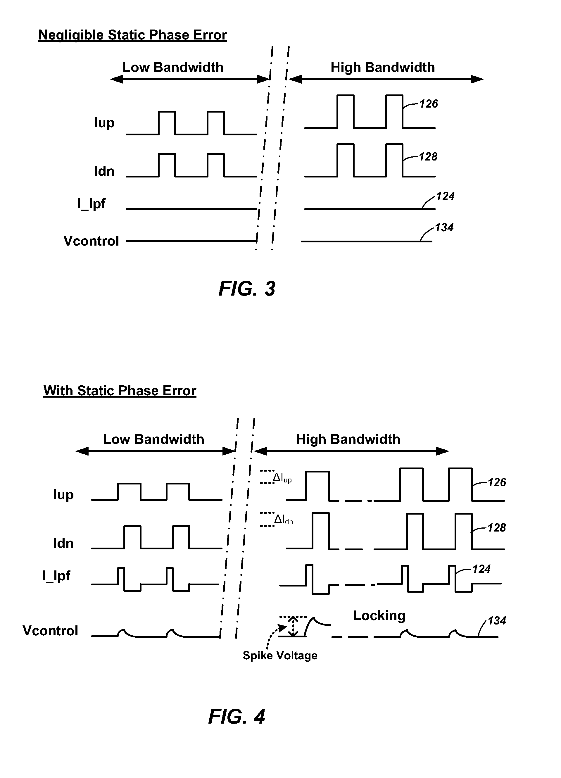
However, large changes in the bandwidth of a PLL can cause large frequency spikes, which may fail the frequency spike requirements.

Method used


Image

  • Methods and apparatuses for incremental bandwidth changes responsive to frequency changes of a phase-locked loop
  • Methods and apparatuses for incremental bandwidth changes responsive to frequency changes of a phase-locked loop
  • Methods and apparatuses for incremental bandwidth changes responsive to frequency changes of a phase-locked loop

Examples


Embodiment Construction

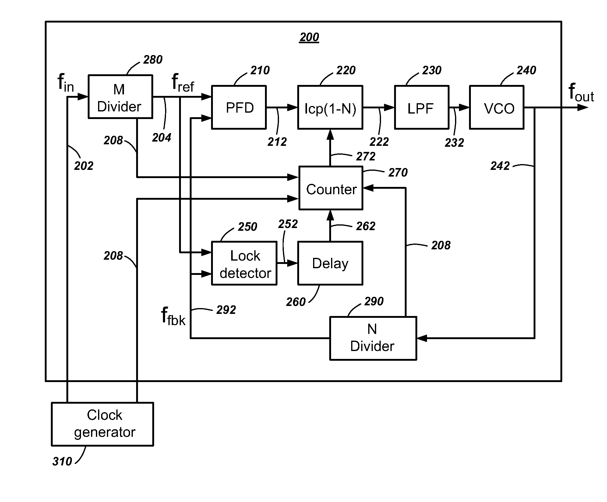
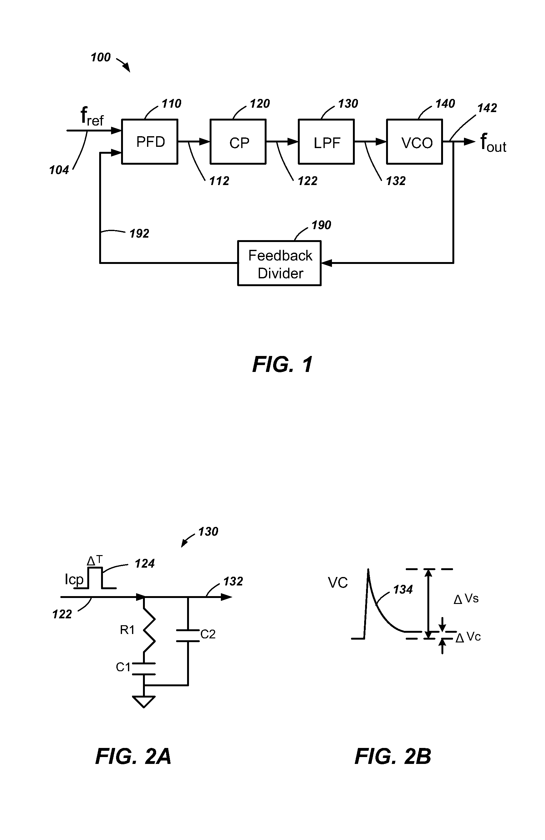
[0021]Embodiments of the present invention include methods of phase locking to a reference clock and phase-locked loops that adjust to a change in frequency of the phase-locked loop. The phase-locked loop locks to a new reference frequency and incrementally adjusts a loop bandwidth in response to the frequency change.

[0022]In this description, circuits and functions may be shown in block diagram form in order not to obscure the present invention in unnecessary detail. Conversely, specific circuit implementations shown and described are exemplary only and should not be construed as the only way to implement the present invention unless specified otherwise herein. Additionally, block definitions and partitioning of logic between various blocks is exemplary of a specific implementation. It will be readily apparent to one of ordinary skill in the art that the present invention may be practiced by numerous other partitioning solutions. For the most part, details concerning timing conside...


PUM


Abstract

In a phase-locked loop, a desired change in frequency is indicated. The phase-locked loop locks to the new frequency and a loop bandwidth of the phase-locked loop is changed. In changing the loop bandwidth, a frequency adjustment signal to a voltage-controlled oscillator may include a voltage spike. The voltage spike is reduced by detecting a lock when the reference clock and a feedback clock reach a same frequency, then waiting for a time delay after the detecting the lock, and adjusting a current level of a charge pump pulse by an incremental amount to achieve a fractional portion of a new loop bandwidth. The charge pump pulse is filtered to generate the frequency adjustment signal and the frequency spike reduction process is repeated until the new loop bandwidth is achieved.

Description

TECHNICAL FIELD[0001]Embodiments of the present disclosure relate generally to phase-locked loops and, more particularly, to methods and apparatuses for adjusting a loop bandwidth of the phase-locked loops.BACKGROUND[0002]In modern high frequency integrated circuits, it is often necessary to generate internal clocks at different frequencies from a reference clock. Conventionally, a Phase-Locked Loop (PLL) or a Delay-Locked Loop (DLL) has been used to generate a clock at the different frequency.[0003]Devices in a computer, such as a CPU, a memory and a video card, normally operate at a standard frequency. However, in order to achieve higher performance, many consumers “overclock” the normal operating frequency of these devices, making them operate faster due to the higher clock frequency. This overclocking can cause a number of problems. Some of these problems may be improper function of the device because it cannot operate properly at the higher frequency and overheating of the devi...

Claims


Application Information

Patent Timeline
Patent Type & Authority Applications(United States)
IPC IPC(8): H03L7/06
CPCH03L7/1072
Inventor SONG, ANFEI
Owner INTEGRATED DEVICE TECH INC
Learn More