Simple zero voltage switching full-bridge DC bus converters

a converter and full-bridge technology, applied in the direction of electric variable regulation, process and machine control, instruments, etc., can solve the problems of inability to give efficiency data, additional power loss, and difficulty in getting timing control signals during the short period, so as to reduce the power loss of the primary fet, reduce the loss of turn-on switching, and increase the conduction loss

Inactive Publication Date: 2006-12-14
INTERNATIONAL RECTIFIER COEP
View PDF5 Cites 33 Cited by
  • Summary
  • Abstract
  • Description
  • Claims
  • Application Information

AI Technical Summary

Benefits of technology

[0010] According to a feature of the invention, ZVS is achieved by increasing the magnetizing current of the transformer. According to a preferred embodiment, this may be done by providing a small air gap in the transformer, which increases the magnetizing current so that during dead times the increased magnetizing current can support the output current and discharge output capacitors of the primary FETs, which will be turned on during the next period.
[0018] The solution is demonstrated in a practical 240 W DC bus converter. The ZVS solution may not reduce power losses of the primary FETs, since reduction of turn-on switching loss comes at the expense of increased conduction loss and increased turn-off loss. However, ZVS has the considerable advantages of reducing losses on the secondary, especially due to body diode conduction and voltage spikes across the secondary synchronous rectifiers, allowing use of lower voltage rating devices, increasing full load efficiency, improving EMI, and enhancing transformer flux balance without asymmetrical bridge currents.

Problems solved by technology

However, no efficiency data was given, and the leakage inductance may result in additional power loss.
For DC bus converters, the dead time is usually less than 100 ns, and to get timing control signals during that short period would be very difficult.

Method used


Image

  • Simple zero voltage switching full-bridge DC bus converters
  • Simple zero voltage switching full-bridge DC bus converters
  • Simple zero voltage switching full-bridge DC bus converters

Examples


Embodiment Construction

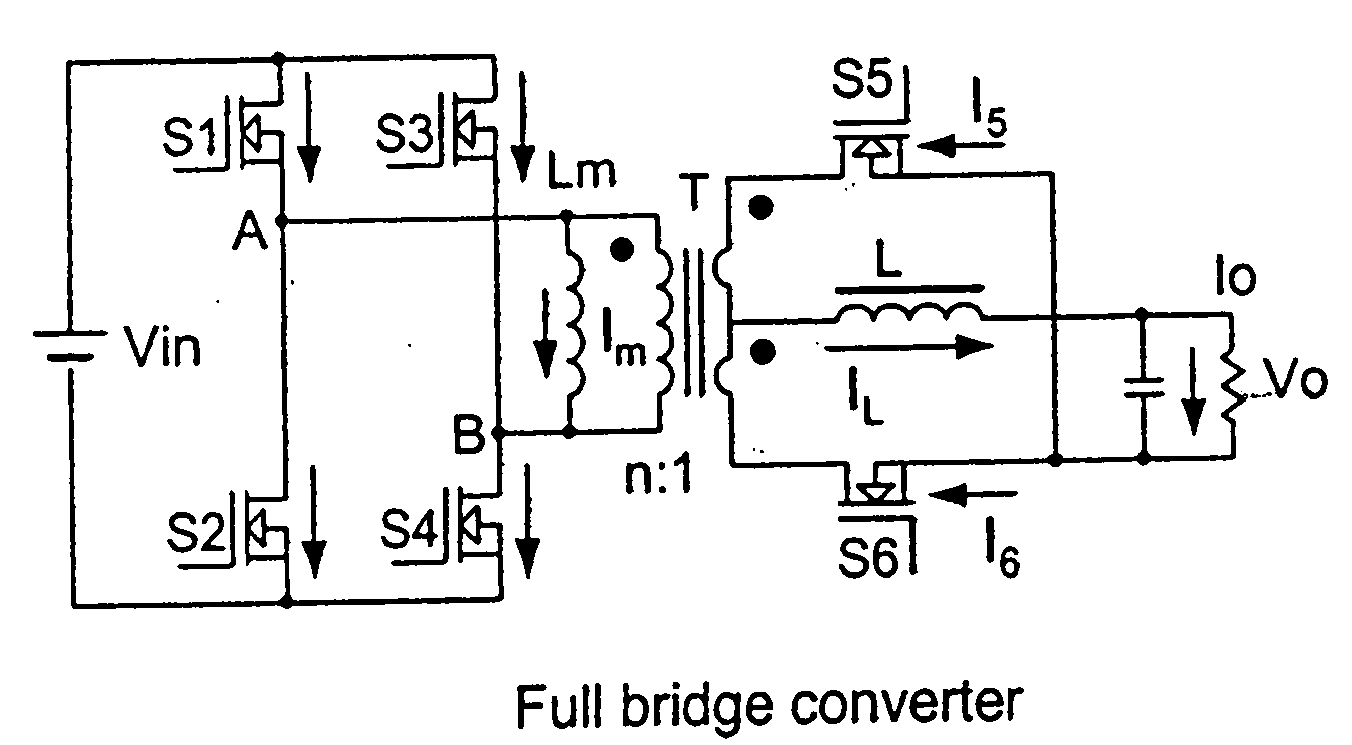
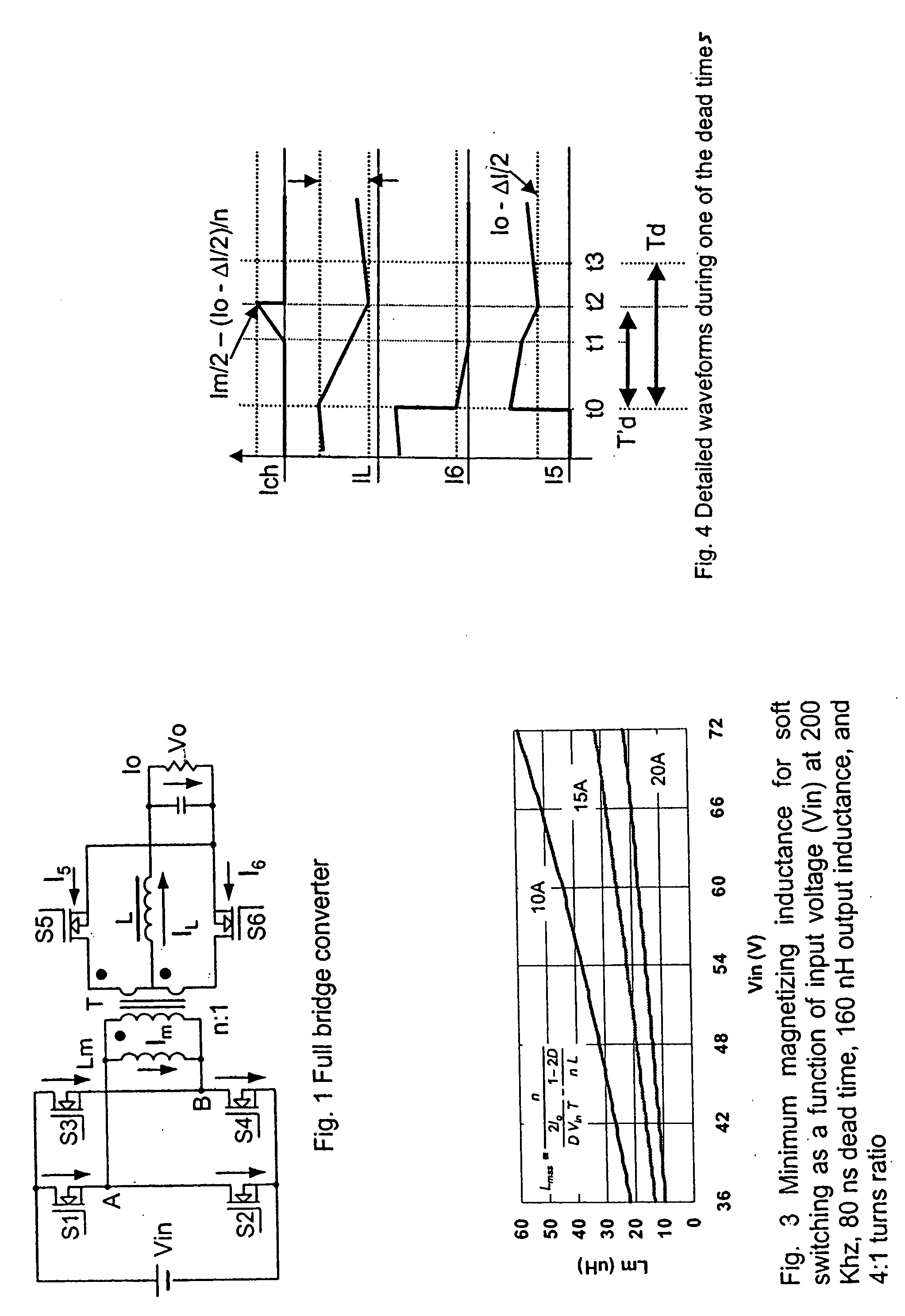
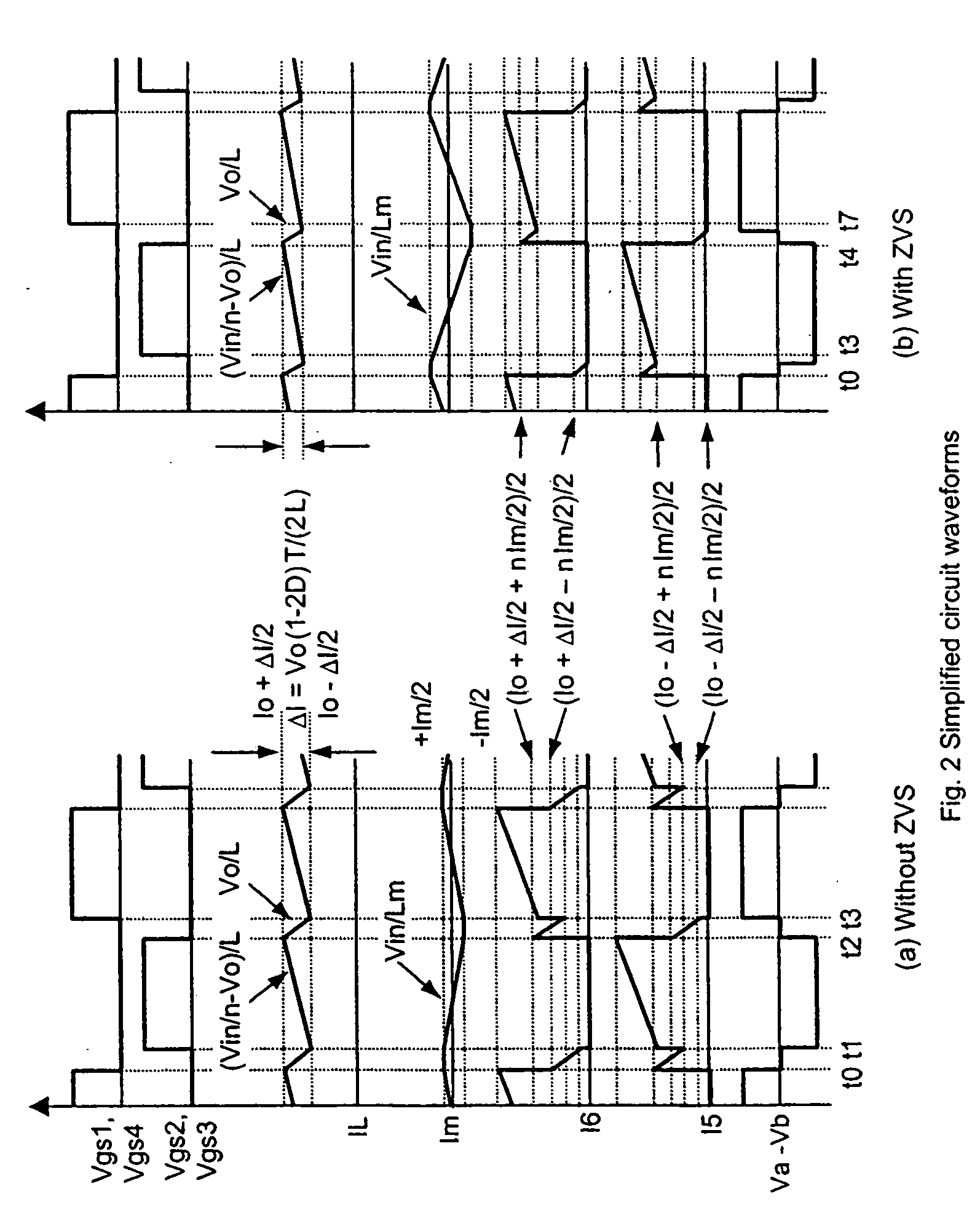
[0031] An isolated full-bridge dc-dc converter with self-driven secondary synchronous rectification is shown in FIG. 1. FIG. 2(a) shows simplified circuit waveforms for a normal hard-switched operation, without ZVS. These waveforms assume that S1 and S4 have the same pulse width (Vgs1 and Vgs4) as S2 and S3 (Vgs2 and Vgs3). Therefore, the magnetizing current is symmetrical. The input and output capacitance is assumed very high, so that output inductor current ripple changes linearly, and is in continuous conduction mode.

[0032] In the hard-switched case of FIG. 2(a), the primary magnetizing current moves to the secondary side during the dead time, and it does not commutate back to the primary side until the beginning of the next switching cycle. During the dead time, the transformer windings are shorted, and the current flowing through the secondary windings can be calculated from the following two equations: I5-I6=nIm2(1)I5+I6=IL(2)

[0033] In (1) and (2), IL is the inductor current...


PUM


Abstract

A method and circuit arrangement for achieving zero voltage switching (ZVS) in a 50% duty cycle full-bridge DC bus converter. The ZVS is obtained by increasing the transformer magnetizing current. During the small dead time between conductions of the two bridge legs, the increased magnetizing current supports the output inductor current, and resonates with MOSFET output capacitance, resulting in ZVS operation. With ZVS operation, body diode conduction and voltage spikes across the secondary synchronous rectifiers are reduced, full load efficiency is increased, and transformer flux balance is enhanced.

Description

CROSS-REFERENCE TO RELATED APPLICATION [0001] This application claims the benefit and priority of U.S. Provisional patent application Ser. No. 60 / 670,830 filed Apr. 13, 2005 entitled SIMPLE ZERO VOLTAGE SWITCHING FULL-BRIDGE DC BUS CONVERTER, the entire disclosure of which is incorporated herein by reference.BACKGROUND OF THE INVENTION [0002] 1. Field of the Invention [0003] The present invention relates to a DC-DC converter, and more particularly to a DC-DC converter adapted for zero-voltage switching in its primary circuit. [0004] 2. Related Art [0005] Half-bridge and full-bridge isolated DC-DC converters with fixed 50% duty cycle are excellent choices for 48V DC bus converters. A half-bridge converter is used at low power levels (below about 150 W). Key benefits of the half-bridge converter are simplicity, robustness and inherent protection against transformer flux imbalance. A full bridge converter is a good choice for higher power levels, or when a better resolution of transfor...

Claims


Application Information

Patent Timeline
Patent Type & Authority Applications(United States)
IPC IPC(8): H02M3/335
CPCH02M3/337H02M1/38Y02B70/10H02M1/0058H02M3/33573
Inventor FAN, WEIDONGSTOJCIC, GORAN
Owner INTERNATIONAL RECTIFIER COEP
Why Eureka
Try Eureka