
Loop bandwidth enhancement technique for a digital PLL and a HF divider that enables this technique

a technology of loop bandwidth and divider, which is applied in the field of wireless communication systems, can solve the problems of insufficient loop bandwidth or excess phase noise in the simple implementation of 23 series cells for certain frequency synthesis applications, and the output frequency has an asymmetrical duty cycle that gets wors

Active Publication Date: 2008-02-21
TEXAS INSTR INC
View PDF12 Cites 31 Cited by
  • Summary
  • Abstract
  • Description
  • Claims
  • Application Information

AI Technical Summary

Benefits of technology

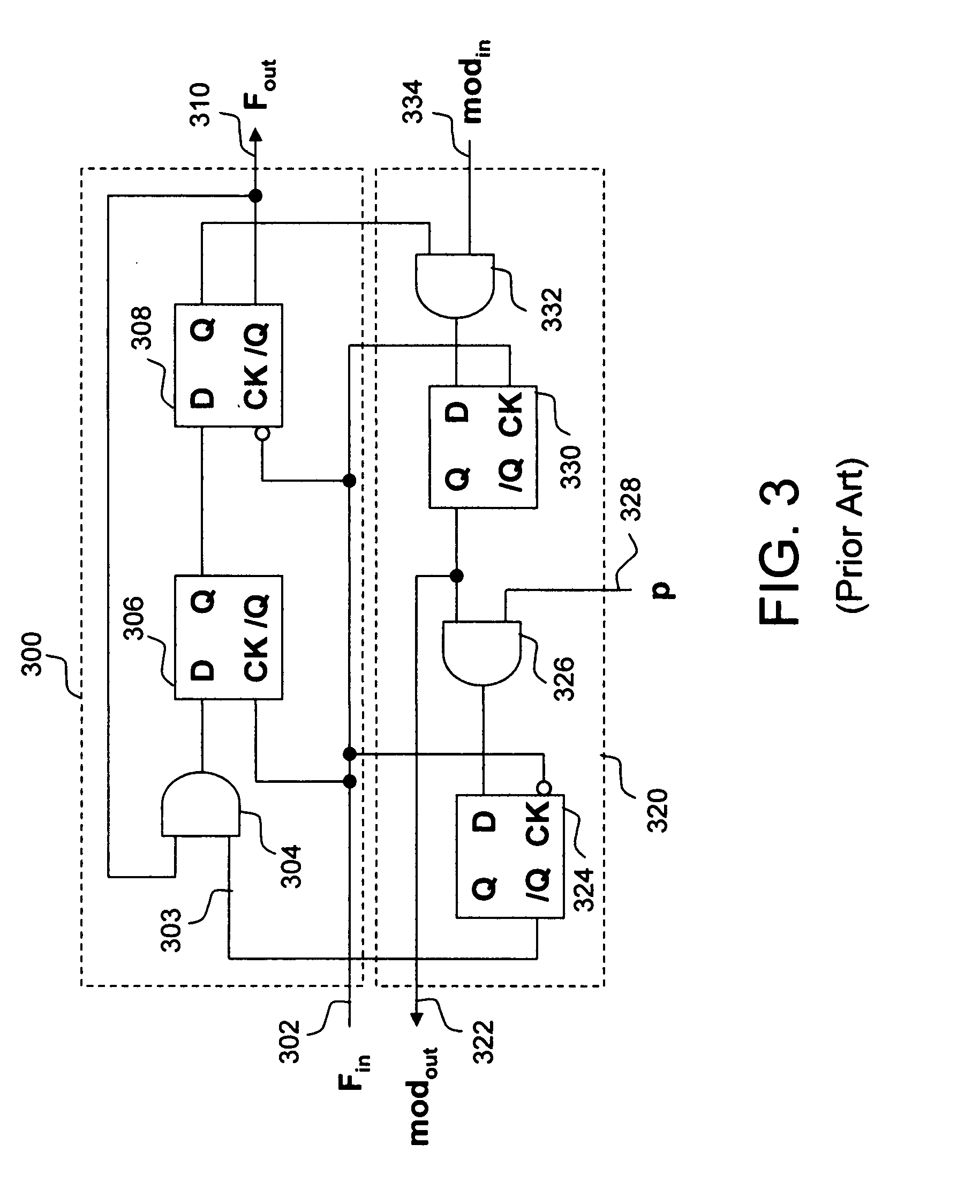
[0011]According to a second embodiment of the present invention, a frequency divider circuit produces an output signal having substantially a 50% duty cycle. The circuit receives an input signal and produces an output signal having a frequency less than a frequency of the input signal. A first frequency divider cell is coupled to the input terminal and receives a first program signal. A second frequency divider cell is coupled between the first frequency divider cell and the output terminal and receives a second program signal. A divide-by-two frequency divider cell receives the output signal and divides it by two.

Problems solved by technology

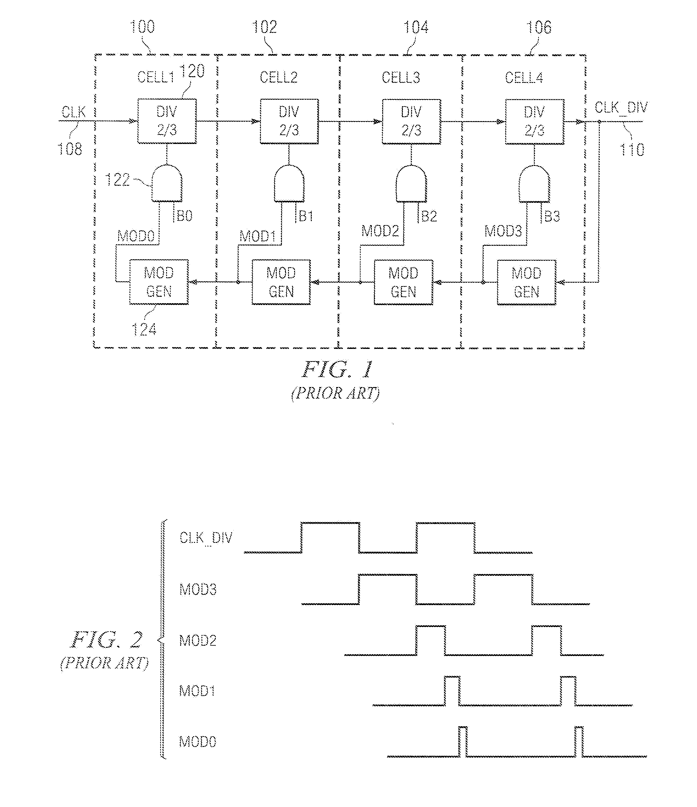
Although the ⅔ series cells of Vaucher et al. is very efficient, it does have limitations for certain applications.
For example, the output frequency has an asymmetrical duty cycle that gets progressively worse with subsequent frequency divisions.
Another limitation is that a straightforward implementation of the ⅔ series cells may have insufficient loop bandwidth or excess phase noise for certain frequency synthesis applications.

Method used


Image

  • Loop bandwidth enhancement technique for a digital PLL and a HF divider that enables this technique
  • Loop bandwidth enhancement technique for a digital PLL and a HF divider that enables this technique
  • Loop bandwidth enhancement technique for a digital PLL and a HF divider that enables this technique

Examples


Embodiment Construction

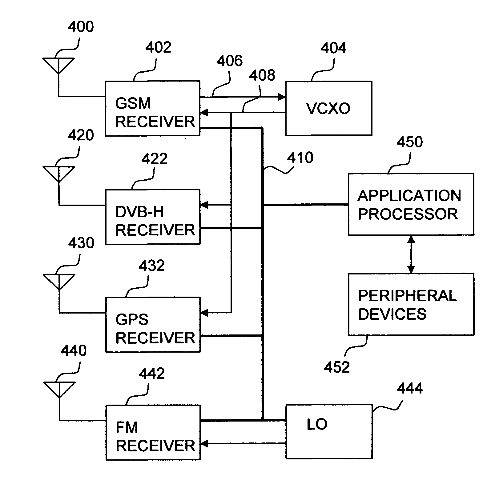
[0027]Referring now to FIG. 4, there is a schematic diagram of a multiple service wireless handset of the present invention. The handset includes four separate receivers. Since each receiver operates on a different carrier frequency, each receiver has a separate antenna. For example, GSM receiver 402 is coupled to antenna 400, DVB-H receiver 422 is coupled to antenna 420, GPS receiver 432 is coupled to antenna 430, and FM receiver 442 is coupled to antenna 440. Each receiver is further coupled to application processor 450 by bus 410. Application processor 450 exchanges baseband signals with each receiver, performs appropriate signal processing operations, and sends resulting signals to respective peripheral devices 452. These peripheral devices preferably include a microphone, speaker, liquid crystal display (LCD), and other appropriate devices. Bus 410 includes data, address, and control signal lines to direct operation of each receiver. The multiple service wireless handset also i...


PUM


Abstract

A method of operating a phase locked loop (FIG. 5) for a wireless receiver is disclosed. The method includes receiving a reference signal (503) having a first and a second plurality of cycles and receiving a feedback signal (512) having the first and the second plurality of cycles. The feedback signal is compared (504) to the reference signal. A plurality of phase errors is produced for each cycle of (UP, FIG. 10A) the first plurality of cycles in response to the step of comparing.

Description

CROSS-REFERENCES TO RELATED APPLICATIONS[0001]This application claims the benefit, under 35 U.S.C. §119(e)(1), of U.S. Provisional Application No. 60 / 822,881 (TI-61884PS), filed Aug. 18, 2006, and incorporated herein by this reference.BACKGROUND OF THE INVENTION[0002]The present embodiments relate to wireless communications systems and, more particularly, to a high frequency programmable frequency divider for frequency modulated (FM) carrier generation for handheld wireless communication systems.[0003]Wireless communications are prevalent in business, personal, and other applications, and as a result the technology for such communications continues to advance in various areas. One such advancement includes the use of spread spectrum communications, including that of code division multiple access (CDMA) which includes wideband code division multiple access (WCDMA) cellular communications. In CDMA communications, user equipment (UE) (e.g., a hand held cellular phone, personal digital ...

Claims


Application Information

Patent Timeline
Patent Type & Authority Applications(United States)
IPC IPC(8): H03D3/24H03K17/04H04R25/00
CPCH03K23/667H03L7/093H04L7/0331H03L7/18H03L7/0991
Inventor NAGARAJ, KRISHNASWAMYSUBBURAJ, KARTHIK
Owner TEXAS INSTR INC
Learn More