Reducing the
loop bandwidth to this value, however, produces a number of drawbacks.
Therefore, reducing the loop bandwidth to a value smaller than the comparison frequency by a factor of ten will produce a commensurate increase in
phase noise and
lock time, which has found to be undesirable for many applications.
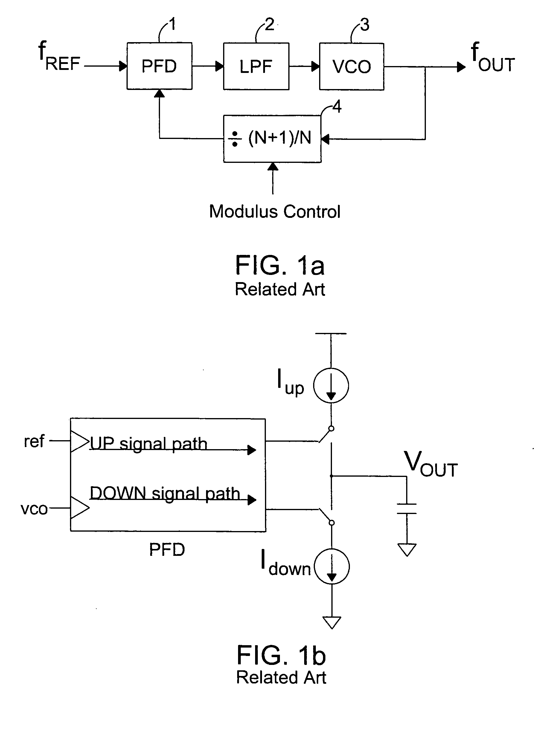
Another drawback of the aforementioned PLL relates to a second type of noise.
This noise appears in the form of spurious signals generated from mismatches that occur, for example, from the
charge pump and the phase and frequency
detector.
These mismatches generate spurious signals which propagate throughout the host
system to degrade performance and therefore, like phase noise, are also considered to be undesirable.
These unsuppressed spurious signals further contribute to the degradation of
signal quality and performance of the host system.
If left uncorrected, the output frequency of the
voltage-controlled oscillator will contain various types of noise, including spurious signals generated from mismatches relating to the phase and frequency detector and the
charge pump.
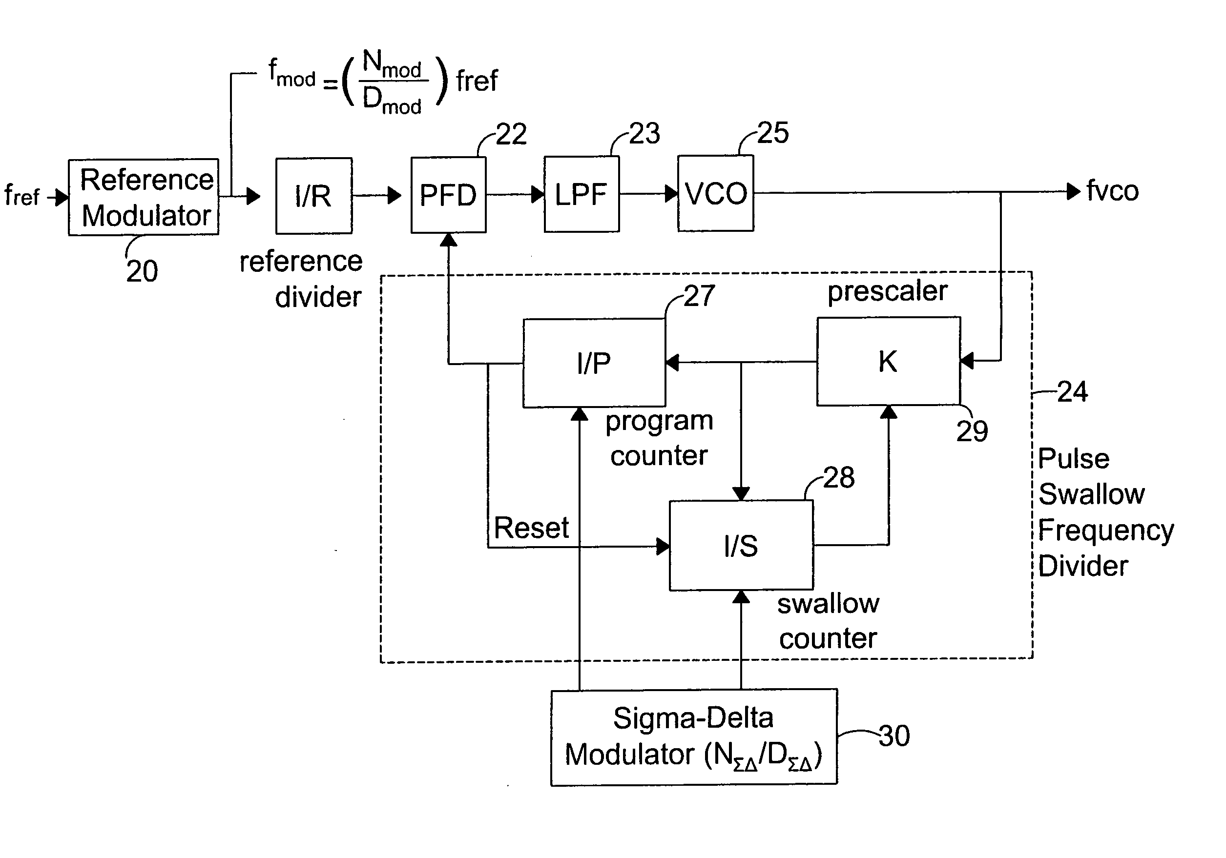
1) The frequency range of the system. If the required frequency range is very narrow and only a few channels exist in the range, only one reference modulator maybe used. However, if the range is very wide, one reference modulator may not be sufficient to achieve a desired degree of spurious signal suppression. In this case, multiple reference modulators maybe included and selectively chosen to achieve an optimal degree of suppression. Tables 2 and 3 (discussed in greater detail infra) include non-limiting example of the values of N.sub.mod and D.sub.mod which may be used to perform the reference
signal modulation of the present invention. If the required frequency range does not include the frequency of 944.65 MHz or 1102.1 MHz, 8 / 9 modulation may be enough for suppression. But, if that frequency is included another modulation such as 5 / 6 may be used for the applicable channel. This multiple reference-modulator embodiment is discussed in greater detail below.
2) The desired spur level for the system.
3) The
loop filter bandwidth, which may be explained as follows. The parameters of the
loop filter depend on the reference frequency. As the reference modulation changes the reference
clock, the loop filter parameters should be changed. If the difference between the original reference
clock and the modulated reference
clock is small, the loop filter can be shared for both the original clock and the modulated clock as long as system specifications such as phase noise, spurious signal suppression, and
lock time allows it. For example, if 8 / 9 modulation and 2 / 3 modulation for a channel shows the same spurious signal suppression, the 8 / 9 modulation may be preferred because the 8 / 9 modulated reference signal is closer to the original reference frequency than the 2 / 3 modulated reference signal.
4) The
hardware complexity of the system. For example, while multiple modulation ratios (3 / 4, 5 / 6, 7 / 8, 8 / 9, etc.) may be acceptable for purposes of achieving a desired level of spurious signal suppression, it may not be possible to achieve all the ratios given the hardware in use. Thus, hardware may be one factor to consider when selecting a modulation ratio in accordance with the present invention.
The first constraint is that 0.ltoreq.S<K and the second constraint is that 0.ltoreq.N.sub..SIGMA..
DELTA.<D.sub..SIGMA..
DELTA.. Actually, these constaints are not algorithmic but practical ones.
Because the range of N.sub..SIGMA..
DELTA. exceeds D.sub..SIGMA..DELTA. for many applications, the
hardware complexity of the Sigma-
Delta modulator increases accordingly.
For comparison purposes, it is noted that a small value of this ratio would not be able to achieve the separation required for
noise suppression.
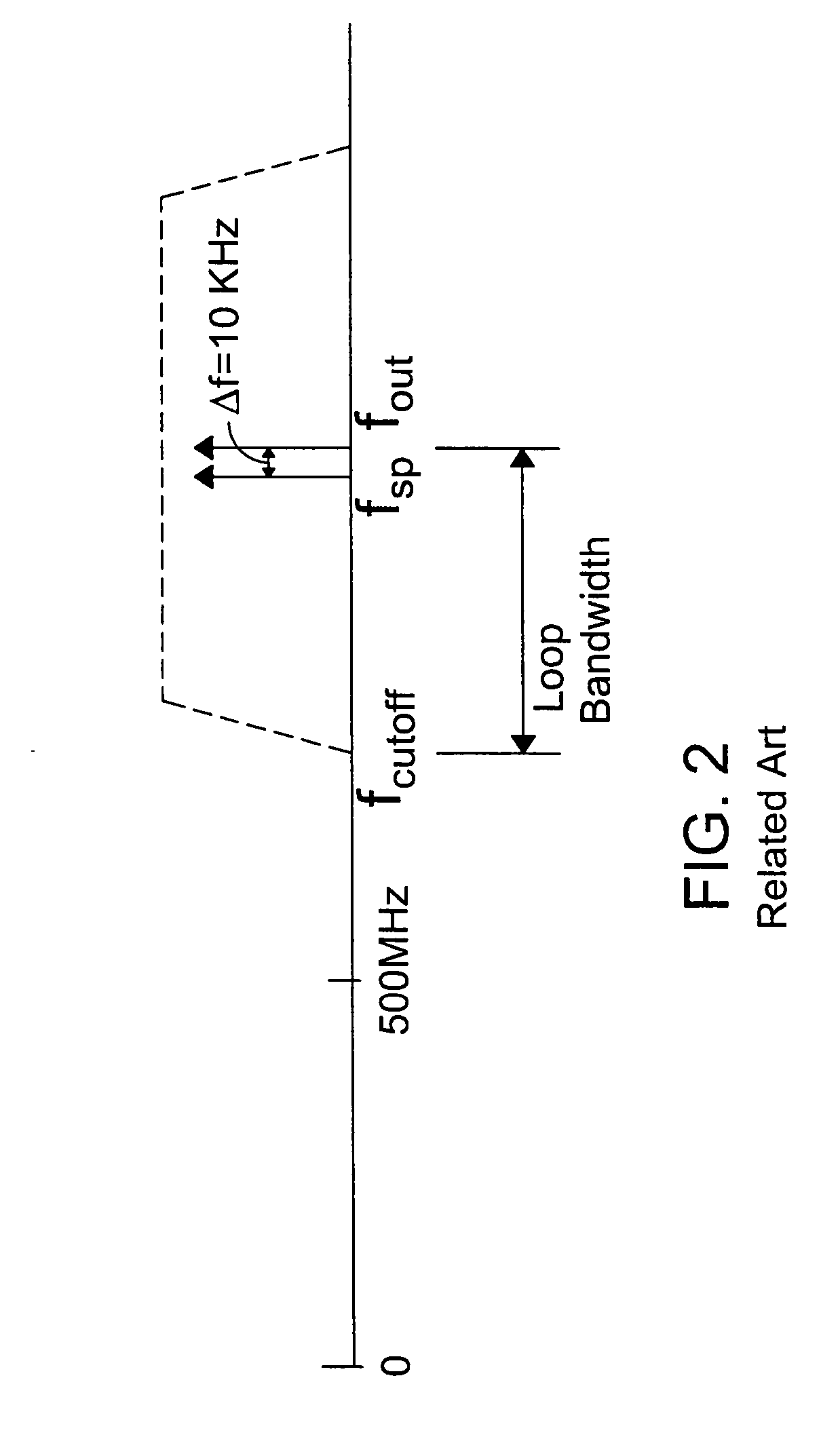
This separation would in most applications lie well within the loop bandwidth of the PLL and thus would not be able to be suppressed by the loop filter.
Because the spurious signal lies within this bandwidth, the loop filter of the FIG. 1(a) PLL will not be able to remove the spurious noise signal from the output frequency.

