
Invisible connecting structure and cabinet

A connecting structure and invisible technology, applied in the direction of connecting components, thin plate connections, furniture connectors, etc., can solve the problems of high technical level requirements for assembly workers, complicated processing and assembly processes, unsatisfactory load-bearing capacity of cabinets, etc., to achieve full utilization The effect of loading space, simple processing, simple and fast assembly

Pending Publication Date: 2019-03-01
李承民
View PDF0 Cites 2 Cited by
  • Summary
  • Abstract
  • Description
  • Claims
  • Application Information

AI Technical Summary

Problems solved by technology

[0002] The current cabinets (such as wardrobes, cabinets, etc.) are mostly made of wood or composite boards connected by nails and glue. First of all, it is difficult to make no connection traces through nails, glue, etc., and the nails will be exposed on the surface of the board. Glue will leave sticking marks, and it is difficult to make the boards fit tightly, which seriously affects the connection quality and appearance
Secondly, its processing and assembly process is complex, inefficient and requires high technical level of assembly workers
Thirdly, the assembly process needs to be completed in the factory, processed into finished products and then transported to the customer, which takes up a lot of space during transportation and is troublesome to carry, and the logistics cost is high
Furthermore, the manufacture of cabinets requires a large number of plundered trees to be made into panels, which destroys the ecological environment
Finally, the load-bearing capacity of the existing cabinet is not ideal

Method used


Image

  • Invisible connecting structure and cabinet
  • Invisible connecting structure and cabinet
  • Invisible connecting structure and cabinet

Examples


Embodiment Construction

[0034] The above and other technical features and advantages of the present invention will be described in more detail below in conjunction with the accompanying drawings.

[0035] In describing the present invention, it should be understood that the terms "center", "longitudinal", "transverse", "length", "width", "thickness", "upper", "lower", "front", " Back", "Left", "Right", "Vertical", "Horizontal", "Top", "Bottom", "Inner", "Outer", "Clockwise", "Counterclockwise", "Axial", The orientations or positional relationships indicated by "radial", "circumferential", etc. are based on the orientations or positional relationships shown in the drawings, and are only for the convenience of describing the present invention, rather than indicating or implying that the referred device or element must have a specific orientation, are constructed and operate in a particular orientation and therefore are not to be construed as limiting the invention.

[0036] In addition, the terms "fir...


PUM

PropertyMeasurementUnit
thicknessaaaaaaaaaa

Abstract

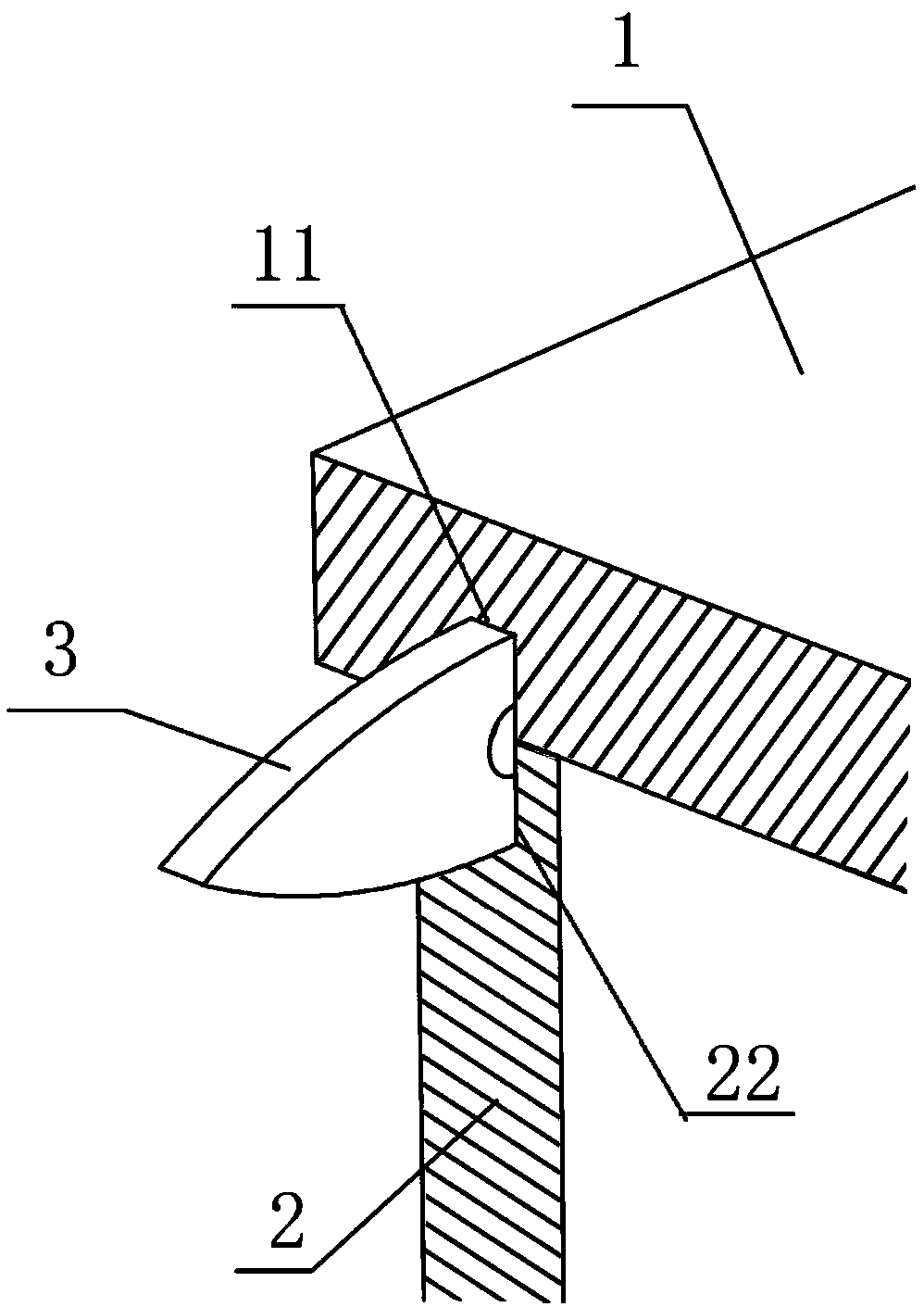
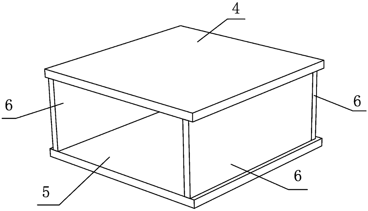
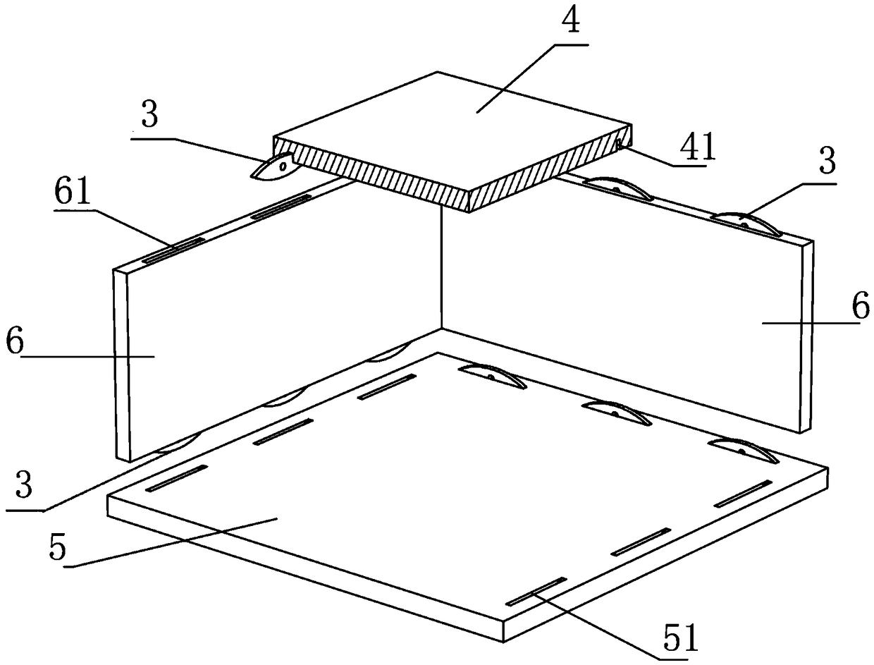
The invention provides an invisible connecting structure and a cabinet. The cabinet comprises a bottom plate, a top plate and side plates, the bottom plate and the top plate are arranged in parallel,and the side plates are located between the bottom plate and the top plate and perpendicularly connected with the bottom plate and the top plate respectively; arc-shaped grooves are formed in the corresponding positions where the side plates, the bottom plate and the top plate are connected respectively, and the grooves are locally formed so as to decrease the rate of damage compared with strip-shaped arrangement. Salix leaf-shaped connecting parts are inserted into the corresponding arc-shaped grooves to connect the bottom plate, the top plate and the side plates, the bottom plate, the top plate and the side plates are ceramic plates, the salix leaf-shaped connecting parts are made from stainless steel pieces, and the outer surfaces of the connecting parts are provided with plastic films.The connecting parts can be hidden in plate bodies which are connected without traces, in this way, machining and assembly efficiency is high, transporting efficiency is high, costs are low, connection is firm, the ceramic plates replace wooden plates, forests are not damaged any more, biological balance is improved, and the effect of load bearing is good.

Description

technical field [0001] The invention relates to the technical field of plate connection, in particular to an invisible connection structure and a cabinet body. Background technique [0002] The current cabinets (such as wardrobes, cabinets, etc.) are mostly made of wood or composite boards connected by nails and glue. First of all, it is difficult to make no connection traces through nails, glue, etc., and the nails will be exposed on the surface of the board. Glue will leave sticking marks, and it is difficult to make the boards fit tightly, which seriously affects the connection quality and appearance. Secondly, its processing and assembly process is complex, inefficient and requires high technical level of assembly workers. Thirdly, the assembly process needs to be completed in the factory, processed into finished products, and then transported to the customer. The transportation takes up a lot of space and the handling is troublesome, and the logistics cost is high. Fu...

Claims


Application Information

Patent Timeline
Patent Type & Authority Applications(China)
IPC IPC(8): A47B96/20F16B5/00B28D1/04
CPCA47B96/20F16B5/0012B28D1/04A47B2230/0096
Inventor 李承民
Owner 李承民
Learn More