Auxiliary tooling and assembly and disassembly method for axial assembly and disassembly of precision parts of turbine main engine

A technology to assist tooling and parts, applied in metal processing, manufacturing tools, metal processing equipment, etc., can solve the problem of easy scratching of the spindle and precision parts, inability to lift the spindle to the exact position, extrusion of the lower half of the parts, etc. problems, to achieve the effect of good installation consistency, simple structure, and reduced installation difficulty

Active Publication Date: 2020-11-17
CHONGQING JIANGJIN SHIPBUILDING IND
View PDF11 Cites 0 Cited by
  • Summary
  • Abstract
  • Description
  • Claims
  • Application Information

AI Technical Summary

Problems solved by technology

[0003] In the assembly state of the unit, when no precision parts are installed, the center of gravity of the main shaft mainly falls on other non-precision parts that have been installed in place. The axis will be reduced to about 1mm relative to the normal working axis due to the action of gravity. The radial clearance of the rotor is often only a few wires, so when assembling precision parts in this case, the lower half of the parts will be greatly squeezed and the inner surface will be scratched; in the disassembled state, the center of gravity of the rotor will fall On precision parts, if the precision parts are directly removed axially, it is bound to cause damage
Therefore, in order to facilitate the axial assembly and disassembly of precision parts, the main shaft needs to be lifted to its normal operating position. However, the common jacking tooling in the prior art is a jack or similar tooling, which is easy to scratch the main shaft and precision parts, and cannot Raise the spindle to the exact position, poor assembly operability

Method used


Image

  • Auxiliary tooling and assembly and disassembly method for axial assembly and disassembly of precision parts of turbine main engine
  • Auxiliary tooling and assembly and disassembly method for axial assembly and disassembly of precision parts of turbine main engine
  • Auxiliary tooling and assembly and disassembly method for axial assembly and disassembly of precision parts of turbine main engine

Examples


Embodiment Construction

[0047] Embodiments of the present invention will be described in further detail below in conjunction with the accompanying drawings.

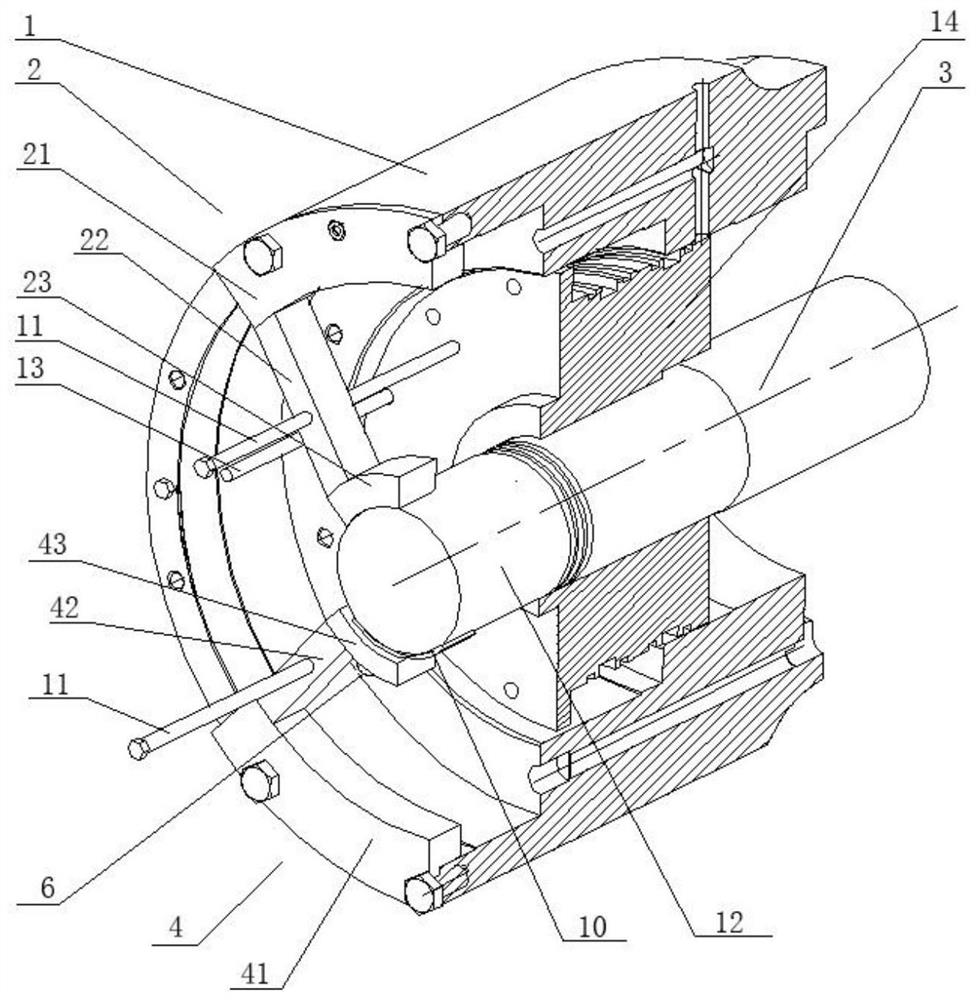
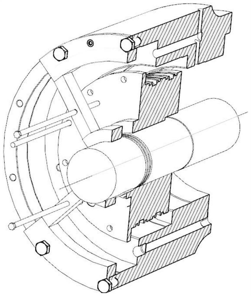
[0048] The positioning tool 2, the lifting tool 4 and the pushing tool in the auxiliary tooling of the present invention are symmetrically arranged on the end faces of both sides of the cylinder body,figure 1 What is shown is the auxiliary tooling installed on one side of the cylinder body, while the other side is omitted and not shown. figure 1 The A line in the figure is the axis of the cylinder body and the positioning tool, and the B line is the axis when the main shaft is not lifted.

[0049] see Figure 1-Figure 6 , an auxiliary tool for the axial assembly and disassembly of precision parts of a turbine main engine, including a positioning tool 2, the positioning tool 2 is arranged on the upper part of the end face of the cylinder body 1, and is fixedly connected with the end face of the cylinder body 1, and the positioning tool 2 It inc...


PUM


Abstract

The invention discloses an auxiliary tool of a turbine main machine for axially mounting and dismounting precise parts and a mounting and dismounting method. The auxiliary tool comprises positioning tools, hoisting tools and pushing tools; the positioning tools comprise outer rings a, support rods a and inner rings a; the hoisting tools comprise outer rings b, support rods b and inner rings b; theinner rings b penetrate through first thread holes; jacking screw rods are mounted in the first thread holes; the pushing tools push the precise parts into or outside a mounting part in the axial direction of a main shaft; and the positioning tools, the hoisting tools and the pushing tools are symmetrically arranged on two side end surfaces of a cylinder block. The method comprises the followingsteps: the precise parts are pushed in front of the mounting part in the cylinder block along the main shaft; the positioning tools and the hoisting tools are mounted; the jacking screw rods are tightened to eject and hoist the main shaft; the precise parts are pushed into the mounting part of the cylinder block by using the screw rod; and the positioning tools and the hoisting tools are dismounted. The auxiliary tool is simple in structure and excellent in mounting consistency, reduces the mounting difficulty under the precondition of guaranteeing the mounting precision, and guarantees no surface damage of the main shaft and the precise parts.

Description

technical field [0001] The invention belongs to the technical field of auxiliary tooling for axially installing components, and in particular relates to an auxiliary tooling for axially installing and disassembling precision components of a turbine main engine and an assembly and disassembly method. Background technique [0002] In the machinery industry, the axial installation of precision parts is often involved. In order to meet the design standards, all parts must be closely matched, especially the parts that cooperate with the rotor, such as bearings, mechanical seals and other high-precision parts. These components are expensive and play a vital role in the unit. At the same time, they need to meet the requirements of fast and accurate disassembly and assembly when the unit is overhauled after operation. Therefore, in the design of the unit, the axial installation of precision parts has become the top priority of the design. [0003] In the assembly state of the unit,...

Claims


Application Information

Patent Timeline
Patent Type & Authority Patents(China)
IPC IPC(8): B23P19/06
CPCB23P19/06
Inventor 何嘉琪李鹏春郭擎唐密
Owner CHONGQING JIANGJIN SHIPBUILDING IND
Why Eureka
Try Eureka