Blind pin puller

A pin puller and blind pin technology, applied in the field of blind pin pullers, can solve the problems of cumbersome operation and complex structure, and achieve the effect of convenient operation.

Pending Publication Date: 2019-03-01
无锡哨东自动化技术有限公司
View PDF1 Cites 4 Cited by
  • Summary
  • Abstract
  • Description
  • Claims
  • Application Information

AI Technical Summary

Problems solved by technology

Complex structure and cumbersome operation

Method used


Image

  • Blind pin puller
  • Blind pin puller
  • Blind pin puller

Examples


Embodiment Construction

[0028] The specific implementation of the blind pin puller of the present invention will be described in detail below in conjunction with the accompanying drawings.

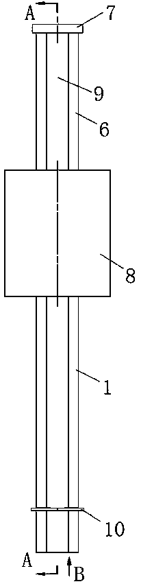
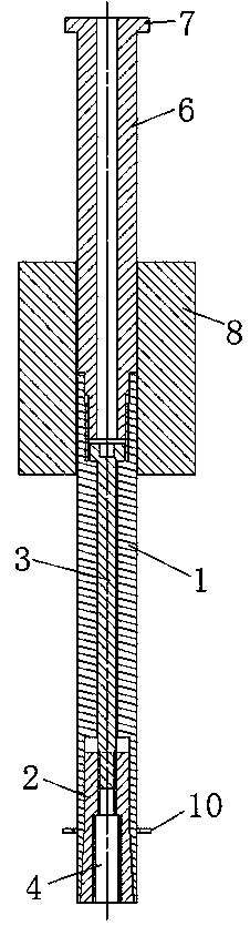
[0029] See attached Figures 1 to 3 , The blind pin puller includes a front tie rod 1, a collet 2 and a central screw 3, a through hole is opened in the middle of the front tie rod 1, the lower end of the front tie rod 1 is a counterbore, and the end of the counterbore at the lower end is a tapered bell mouth, The upper end of the front pull rod 1 is a counterbore.

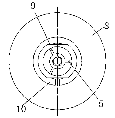
[0030] The upper end of collet 2 is that the lower end of the cylinder is a tapered head with a large bottom and a small top. The upper end of collet 2 is a screw hole, and the lower end is a pin-drawing hole 4, and the pin-pulling hole 4 communicates with the screw hole. The hole arm of the pin pulling hole 4 has three grooves 5 to the lower end, and the three grooves 5 are evenly distributed on the circumferential surface of the pin pulling hole 4...


PUM


Abstract

The invention relates to the technical field of mechanical mounting equipment and discloses a blind pin puller. The blind pin puller comprises a front pull rod, a chuck and a center screw. A through hole is formed in the middle of the front pull rod, the lower end of the front pull rod is a counter bore, the end part of the counter bore in the lower end is a cone-shaped horn mouth, the upper end of the front pull rod is a counter bore, the upper end of the chuck is a cone-shaped head, the lower end of the cylinder body of which is big on the lower side but small on the upper side, the upper end of the chuck is a screw hole while the lower end of the chuck is a pin pulling hole, an open slot is formed from a hole arm of the pin pulling hole to the lower end, the cone-shaped face of the cone-shaped head of the chuck is matched with the cone-shaped horn mouth of the front pull rod when the chuck is matched in the counter bore in the lower end, a distance is formed between the front end ofthe chuck and the bottom of the counter bore in the lower end of the front pull rod, the center screw is formed in the middle through hole of the front pull rod, the thread at the lower end of the center screw is matched with a screw hole in the upper end of the chuck, and the head of the center screw is located in the counter bore in the upper end of the front pull rod. The blind pin puller provided by the invention is simple and feasible and convenient to operate, and does not damage a product body and a pin in the pin pulling process.

Description

technical field [0001] The invention relates to the technical field of mechanical installation equipment, in particular to a blind pin puller. Background technique [0002] At present, the locating pins on many mechanical equipment, engines and other products are positioned using cylindrical pins without holes (we refer to them as "blind pins"). There are no threads on this locating pin, and there is no through hole at the bottom of the pin hole. The surface smoothness requirements for blind pins are also very high. However, during the maintenance of the equipment, the blind pin needs to be pulled out. The method used by the rare blind pin pulling tools on the market will either damage the product body or the outer surface of the pin, so that it cannot be used anymore. All must change pin like this after each maintenance, has caused great waste, does not meet the requirement of present national environmental protection and saving. Either the operation is cumbersome and req...

Claims


Application Information

Patent Timeline
Patent Type & Authority Applications(China)
IPC IPC(8): B25B27/02
CPCB25B27/02
Inventor 张新亮张明
Owner 无锡哨东自动化技术有限公司
Why Eureka
Try Eureka