
Eureka
For R&D, Eureka makes reading and utilizing patents & technical documents easy.
Eureka AIR
Designed for self-driven R&D workflows. Generate viable solutions, solve complex R&D challenges, empower your innovation with AI.

Eureka Materials
Designed for material experts only. Revolutionize your material R&D, from search, analyze, to developing new materials.

TechResearch
Generate reliable direction feasibility study reports for your R&D in just a few steps.

TechSeek
Discover and master advanced knowledge NOW. Basics, ideas, possibilities, all at once.

TechMind
As an expert in R&D Theories, TechMind can generates customized viable solutions instantly.

TechRisk
Analyze your overall solution with one click, know your potential R&D risks in advance.

TechMonitor
Get weekly tech updates, stay abreast of the latest tech innovations and key insights.
Adjustable type discharging cloth applied to production of high-frequency transformer
A high-frequency transformer and discharge cloth technology, which is applied in the direction of transportation, packaging, and slideway, can solve the problems of component drop, trouble, and inconvenient use and storage of discharge cloth, so as to prevent falling and use conveniently quick effect
- Summary
- Abstract
- Description
- Claims
- Application Information
AI Technical Summary
Problems solved by technology
Method used
Image

Examples
Embodiment 1
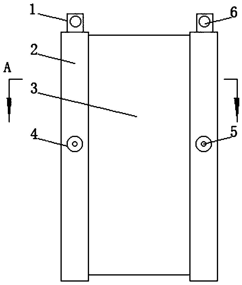
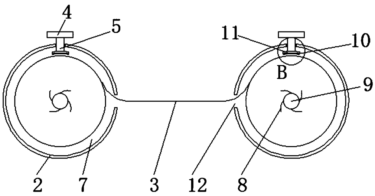
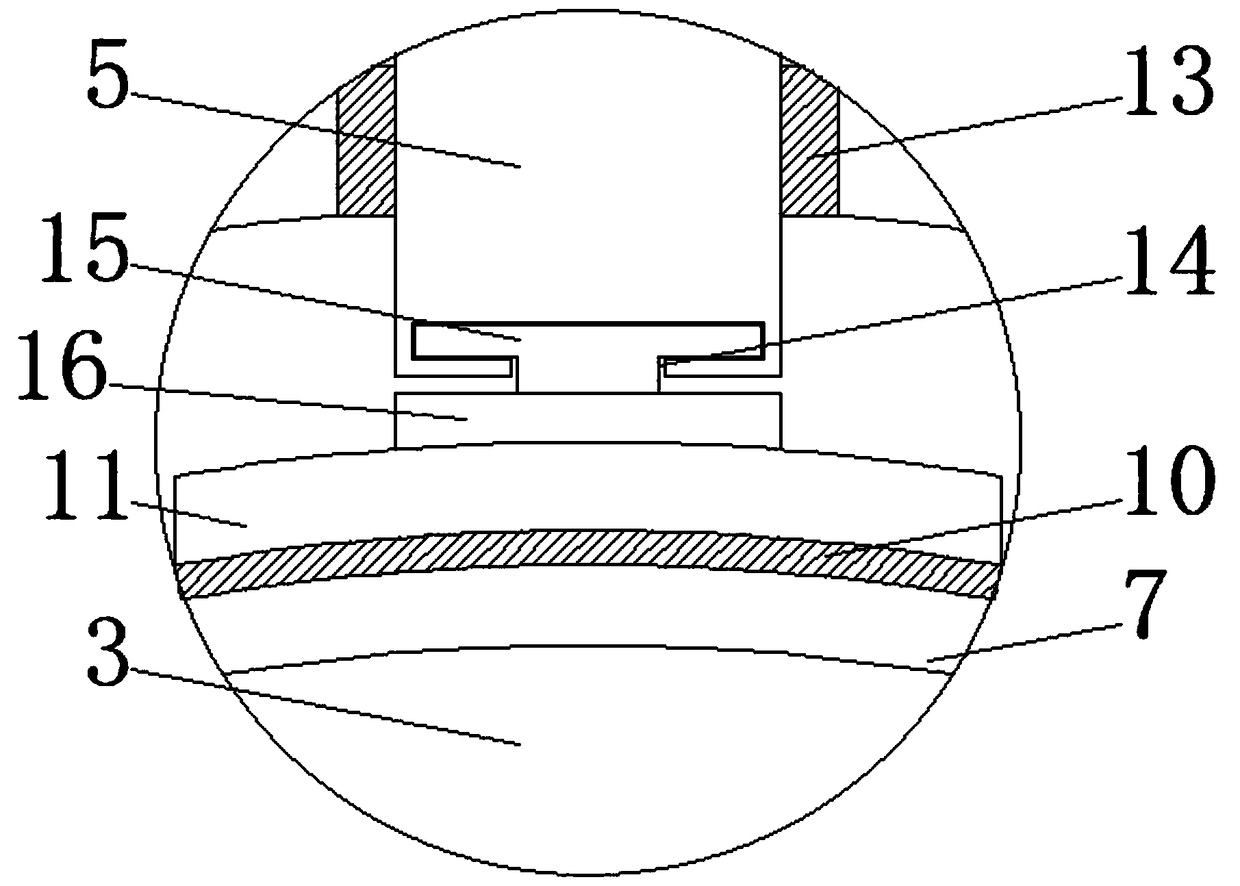
[0016] Embodiment 1, an adjustable discharge cloth for high-frequency transformer production, including a discharge cloth 3, a discharge pipe 2 is provided at both ends of the discharge cloth 3, and an adjustment groove is provided on the inner side of the discharge pipe 2 7. One side of the adjusting groove 7 is provided with a connecting groove 12, and the adjusting groove 7 is provided with a movable shaft 9, the rotating shaft 9 is provided with a ruler spring 8, and the two ends of the discharge cloth 3 are worn. The connecting grooves 12 at both ends of the discharge cloth 3 are evenly wound and connected with the rotating shaft 9 through the ruler spring 8. The middle part of the discharge pipe 2 is provided with a threaded adjustment hole 13, and the threaded adjustment hole 13 is provided with an adjustment shaft 5. The upper end of the adjustment shaft 5 is provided with an adjustment dial 4, and the bottom of the adjustment shaft 5 is provided with a fixed block 11, ...
Embodiment 2
[0019] Embodiment 2, an adjustable discharge cloth for high-frequency transformer production, including a discharge cloth 3, a discharge pipe 2 is provided at both ends of the discharge cloth 3, and an adjustment groove is provided on the inner side of the discharge pipe 2 7. One side of the adjusting groove 7 is provided with a connecting groove 12, and the adjusting groove 7 is provided with a movable shaft 9, the rotating shaft 9 is provided with a ruler spring 8, and the two ends of the discharge cloth 3 are worn. The connecting grooves 12 at both ends of the discharge cloth 3 are evenly wound and connected with the rotating shaft 9 through the ruler spring 8. The middle part of the discharge pipe 2 is provided with a threaded adjustment hole 13, and the threaded adjustment hole 13 is provided with an adjustment shaft 5. The upper end of the adjustment shaft 5 is provided with an adjustment dial 4, and the bottom of the adjustment shaft 5 is provided with a fixed block 11, ...
PUM
 Abstract
Description
Claims
Application Information
 - R&D Engineer
- R&D Manager
- IP Professional
- Industry Leading Data Capabilities
- Powerful AI technology
- Patent DNA Extraction
Browse by: Latest US Patents, China's latest patents, Technical Efficacy Thesaurus, Application Domain, Technology Topic, Popular Technical Reports.
© 2024 PatSnap. All rights reserved.Legal|Privacy policy|Modern Slavery Act Transparency Statement|Sitemap|About US| Contact US: help@patsnap.com