
Self-driven guide rail trolley suitable for curve guide rail

A curved guide rail and self-driven technology, which is applied in the field of guide rail transmission, can solve the problems of increasing system production cost, increasing system complexity, and complex structure of the transmission mechanism, so as to facilitate daily maintenance and repair, facilitate overall miniaturization, and simple overall structure Effect

Pending Publication Date: 2019-03-01
无锡市赛博机电有限公司
View PDF0 Cites 4 Cited by
  • Summary
  • Abstract
  • Description
  • Claims
  • Application Information

AI Technical Summary

Problems solved by technology

[0003] 1. The external transmission mechanism usually uses transmission components such as rack and pinion, screw, worm, friction disc, etc. The structure of the transmission mechanism is complex, which not only increases the production cost of the system, but also causes the system to be large in size, which cannot be used in narrow space applications. limited;
[0004] 2. The complex structure of the transmission mechanism increases the complexity of the system, resulting in poor operating stability of the system in precision occasions and difficulties in daily maintenance and repair;
[0005] 3. The transmission mechanism cannot drive the guide rail trolley system to perform curved movement along the curved guide rail

Method used


Image

  • Self-driven guide rail trolley suitable for curve guide rail
  • Self-driven guide rail trolley suitable for curve guide rail

Examples


Embodiment Construction

[0024] combine figure 1 , which describes a specific embodiment of the present invention in detail, but does not limit the claims of the present invention in any way.

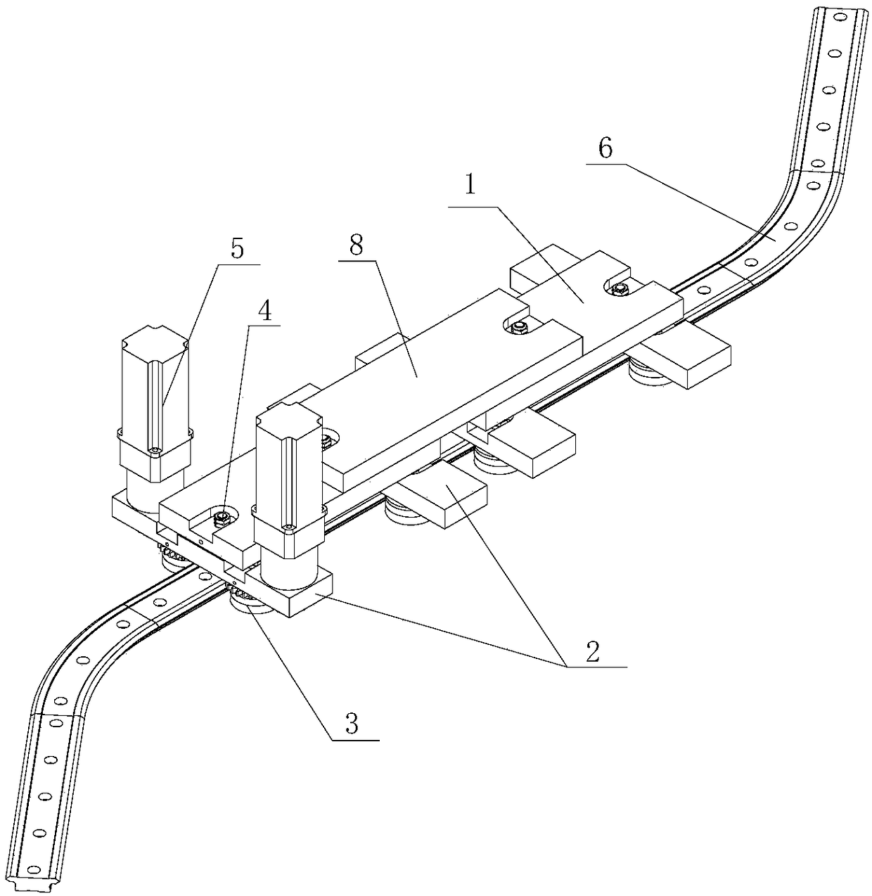
[0025] Such as figure 1 As shown, a self-driven guide trolley suitable for curved guide rails includes an upper loading board 1, two lower loading boards 2, two sets of roller assemblies 3, two sets of steering assemblies 4 and a driving mechanism 5, and each lower loading board 2 is provided with 1 set of roller assemblies 3, the upper loading plate 1 is set above the two lowering plates 2 and is used to horizontally connect the two lowering plates 2, and a set of steering assembly 4 is arranged between the upper loading plate 1 and each lowering plate 2;

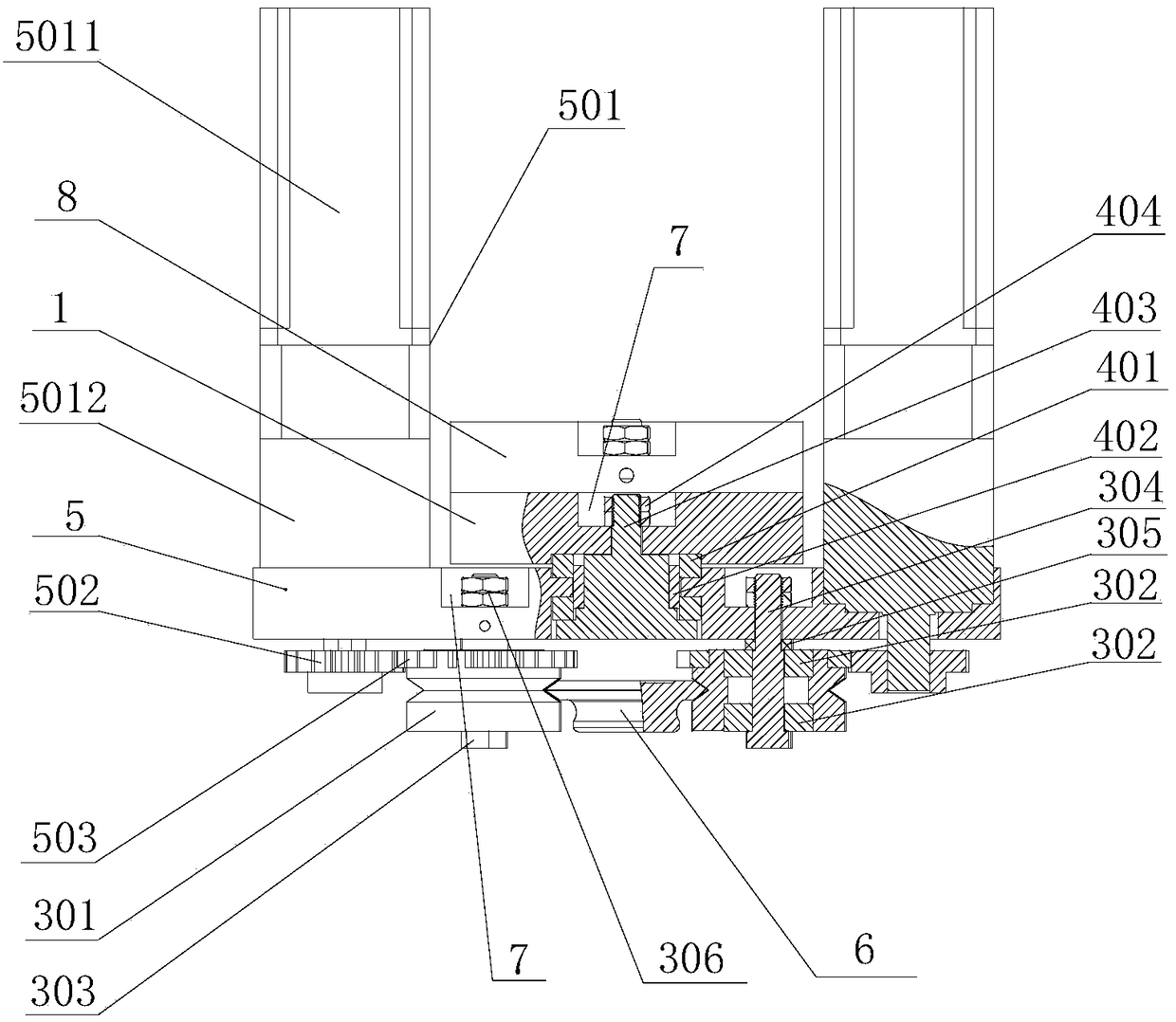
[0026] Each set of roller assemblies 3 includes 2 guide rail rollers 301, 2 sets of bearings, centering bolts 303, eccentric bolts 304, 2 spacers 305 and 2 double nuts 306, and the 2 sets of bearings are respectively embedded in 2 guide rails through inter...


PUM


Abstract

The invention relates to the technical field of guide rail transmission, in particular to a self-driven guide rail trolley suitable for a curve guide rail. The self-driven guide rail trolley comprisesan upper carrying plate, two lower carrying plates, two rolling wheel assemblies, two steering assemblies and a driving mechanism; one rolling wheel assembly is arranged below each lower carrying plate, the upper carrying plate is arranged above the two lower carrying plates and is used for horizontally connecting the two lower carrying plates, one steering assembly used for steering adjustment is arranged between the upper carrying plate and each lower carrying plate, and a guide rail rolling wheel of at least one rolling wheel assembly is matched with the driving mechanism used for drivingthe guide rail rolling wheel to rotate. According to the self-driven guide rail trolley, a transmission mechanism is simple and compact in structure, and only a gear set conducts transmission, so thatthe stability of the transmission mechanism is good, the overall miniaturization of the guide rail trolley is facilitated, and the guide rail trolley is convenient to apply in a narrow space; the guide rail trolley is simple in the overall structure, low in the production cost and convenient for the daily maintenance and repairing; and on the basis of the design of the steering assemblies, the curve movement of the guide rail trolley can be carried out along curve guide rails with any radian and same section.

Description

technical field [0001] The invention relates to the technical field of guide rail transmission, in particular to a self-driven guide rail trolley suitable for curved guide rails. Background technique [0002] With the continuous advancement of industrial automation technology, the trolley that moves linearly along the guide rail, as an automatic carrying mechanism, is widely used in various industries. The drive system of the existing rail trolley transport system is usually composed of a motor, a guide rail, and an external transmission mechanism. This transmission mechanism has the following problems: [0003] 1. The external transmission mechanism usually adopts transmission components such as rack and pinion, screw, worm, friction disc, etc. The structure of the transmission mechanism is complex, which not only increases the production cost of the system, but also causes the system to be bulky, which cannot be used in small space applications. limited; [0004] 2. The ...

Claims


Application Information

Patent Timeline
IPC IPC(8): B65G35/00
CPCB65G35/00
Inventor 俞震
Owner 无锡市赛博机电有限公司
Learn More