
Plant tail water arrangement structure for situation characterized by large amplitude of water level of downstream region

A technology of changing the amplitude of the water level and arranging the structure, which is applied in the fields of water conservancy projects, hydroelectric power generation, hydroelectric power stations, etc. Depth, the effect of reducing excavation workload

Pending Publication Date: 2019-03-01
POWERCHINA CHENGDU ENG
View PDF0 Cites 0 Cited by
  • Summary
  • Abstract
  • Description
  • Claims
  • Application Information

AI Technical Summary

Problems solved by technology

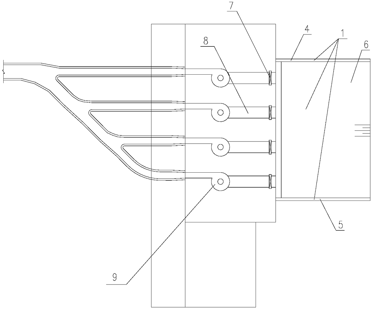
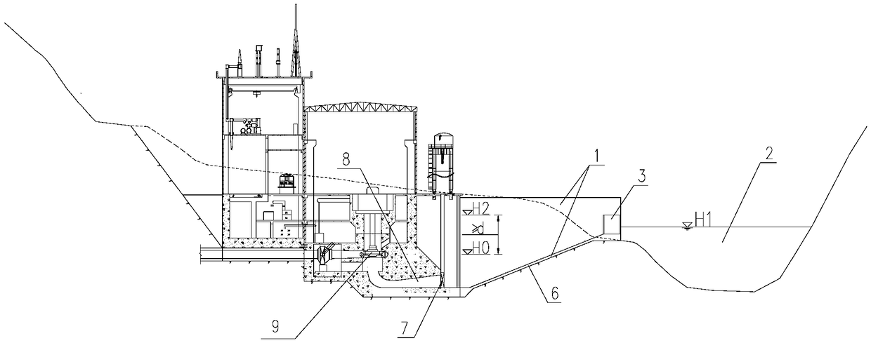
However, when the water level of the downstream channel varies greatly, the structure will have the following problems: 1. When the downstream channel is at a low water level (H 1 ), in order to meet the requirements of the suction height (d), a lower turbine installation elevation (H 0 ), the depth of the foundation pit of the powerhouse of the hydropower station will be deepened accordingly, and the excavation volume of the foundation pit will also increase significantly; Sediment is easy to deposit in the tailrace, affecting the normal operation of the hydropower station
The main problem of this structure is: because the overflow weir is set at the end of the tailrace, and the overflow weir raises the outlet elevation of the tailrace, the discharge capacity of the tailrace will also decrease accordingly. When the hydropower station generates power at full capacity, the tailrace The water level inside will rise sharply, which will bring greater flood control pressure to the main factory building

Method used

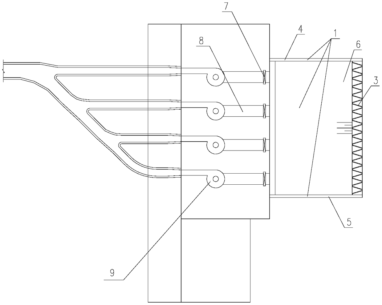

Image

  • Plant tail water arrangement structure for situation characterized by large amplitude of water level of downstream region
  • Plant tail water arrangement structure for situation characterized by large amplitude of water level of downstream region
  • Plant tail water arrangement structure for situation characterized by large amplitude of water level of downstream region

Examples


Embodiment Construction

[0018] like figure 2 , image 3 Shown is a tailwater layout structure for powerhouses with large fluctuations in downstream water levels that can meet the flood control requirements for full-load power generation without greatly increasing the depth of excavated foundation pits provided by the present invention. The tailwater layout structure of the powerhouse includes a reverse slope tailrace 1, and a large overflow thin-walled weir 3 is also arranged on the side where the reverse slope tailrace 1 is connected to the downstream channel 2, and the large overflow The crest elevation of the thin-walled weir 3 meets the following requirements,

[0019] The crest elevation of the large overflow thin-walled weir (H 2 )-turbine installation elevation (H 0 ) ≥ suction height (d). The present application improves the existing linear thin-walled overflow weir into a large overflow thin-walled weir, and arranges the large overflow thin-walled weir in a channel connected with the re...


PUM


Abstract

The invention discloses a plant tail water arrangement structure, particularly discloses a plant tail water arrangement structure for the situation characterized by the large amplitude of the water level of a downstream region, and belongs to the technical field of water resource and hydroelectric engineering building design and construction. The plant tail water arrangement structure for the situation characterized by the large amplitude of the water level of the downstream region is provided, can meet the requirement for flood control in the full-load power generation process, and cannot cause the large increase of the depth of an excavated foundation pit. The plant tail water arrangement structure comprises a counter slope type tail water channel. A large overflowing sharp-crested weiris further arranged on the side, connected with a downstream river channel, of the counter slope type tail water channel. The weir crest level of the large overflowing sharp-crested weir meets the following requirement that the difference of the weir crest level (H2) of the large overflowing sharp-crested weir and the water turbine installation elevation (H0) is larger than or equal to the suctionheight (d).

Description

technical field [0001] The invention relates to a powerhouse tailwater layout structure, in particular to a powerhouse tailwater layout structure used for downstream water levels with large fluctuations, and belongs to the technical field of water conservancy and hydropower engineering building design and construction. Background technique [0002] At present, the layout of the tail water structure of the powerhouse of the hydropower station is usually as follows: figure 1 structure shown. The tailrace structure of the existing powerhouse with this structure mainly includes the following technical features: 1. From upstream to downstream, the tailrace structure is composed of a draft pipe, a tailgate gate and a tailrace channel respectively, wherein the tailrace channel includes the side wall of the tailrace channel and the tailrace channel There are two parts of the bottom plate; 2. The bottom plate of the tailrace channel is connected with the downstream river channel by ...

Claims


Application Information

Patent Timeline
Patent Type & Authority Applications(China)
IPC IPC(8): E02B9/06
CPCE02B9/06Y02E10/20
Inventor 张公平唐志丹唐忠敏陈钰鑫
Owner POWERCHINA CHENGDU ENG
Learn More