
Prefabricated shear wall vertical steel bar positioning device

A technology of vertical reinforcement and prefabricated shear force, applied to structural elements, building components, building reinforcements, etc., can solve the problems of time-consuming and consumable materials, low positioning accuracy, and low versatility

Pending Publication Date: 2019-03-01
NANTONG SIJIAN CONSTR GRP
View PDF0 Cites 7 Cited by
  • Summary
  • Abstract
  • Description
  • Claims
  • Application Information

AI Technical Summary

Problems solved by technology

The problems existing in this method during use are: 1. The processed steel plate can only correspond to the prefabricated shear wall with the same wall size and vertical reinforcement position, and the versatility is not high; 2. When the wall is too long, the entire wall After the concrete is poured, the steel plate will be stuck by the vertical steel bars and cannot be removed smoothly. It can only be taken out by forcefully prying it out or cutting it in pieces. This makes the steel plate unable to be reused and can only be reprocessed, which consumes time and materials; To improve the integrity of prefabricated buildings, more and more horizontal reinforcement bars of prefabricated shear walls have been changed from straight lines to closed "U" shapes. The precise positioning measures make the positioning accuracy not high, resulting in the situation that the prefabricated shear wall cannot be installed and the "U"-shaped horizontally distributed steel bars are cut

Method used


Image

  • Prefabricated shear wall vertical steel bar positioning device
  • Prefabricated shear wall vertical steel bar positioning device
  • Prefabricated shear wall vertical steel bar positioning device

Examples


Embodiment

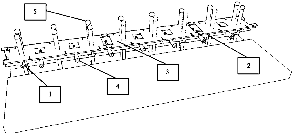
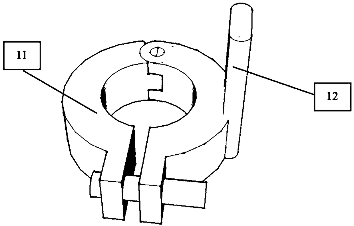
[0028] Transfer layer construction: after the completion of the traditional reinforcement project, the cast-in-place reinforcement mesh in the prefabricated vertical reinforcement pre-embedded area of ​​the prefabricated shear wall is first fixed as a whole, and then the two ends and the middle of the prefabricated wall are pre-embedded according to the vertical reinforcement pre-embedded drawing. Eight vertical steel bars; then, set the horizontal line on the pre-embedded vertical steel bars and install the elevation clip 1, the elevation clip 1 is fixed by a pair of semicircular hoops 11 to hold the steel bars tightly, when the elevation clip 1 is installed It is necessary to ensure that the top surface of the semi-circular hoop 11 is at the same level as the horizontal line, and that the limit block 12 faces the outside of the wall and is parallel to the wall, and install the elevation clip 1 on other pre-embedded steel bars in this way;

[0029] After all the elevation clip...


PUM


Abstract

The invention relates to a prefabricated shear wall vertical steel bar positioning device which comprises an elevation clamp, positioning angle steel, a positioning steel sleeve plate, a screwing partand a steel bar protecting pipe. The elevation clamp consists of two semicircular hoops, one semicircular hoop is provided with a protruded limiting block, the positioning angle steel is provided with a rib, a steel bar positioning groove and a screwing hole, and the other side is provided with evenly spaced fixing holes; two sides of the positioning steel sleeve plate formed in the positioning steel sleeve plate are provided with fixing grooves connected with the positioning angle steel fixing holes in the wall direction, the middle and two ends of the steel sleeve plate are provided with pouring ports facilitating concrete pouring, and the two ends are provided with a web plate and a compressing plate which are centrosymmetric. The end, close to a handle, of the screwing part is provided with a limiting thrust bearing, and the end, away from the handle, of the screwing part is provided with a screwing nut. The steel bar protecting pipe is a PVC pipe with one closed end. By adoptingthe scheme, accurate positioning of prefabricated shear wall vertical steel bars and cast-in-situ edge member vertical steel bars can be achieved.

Description

technical field [0001] The invention relates to a vertical reinforcement positioning device for a prefabricated shear wall, which belongs to the technical field of building materials. Background technique [0002] Practices at home and abroad have shown that prefabricated buildings have significant advantages, which are conducive to reducing labor, shortening construction periods, reducing resource consumption, reducing construction waste and dust, etc., and are conducive to improving production efficiency, improving construction safety and project quality; The construction accuracy also puts forward more stringent requirements. For example, whether the positioning accuracy of the vertical reinforcement of the prefabricated shear wall in the prefabricated shear wall structure meets the requirements is an important factor related to the overall quality and construction period of the prefabricated building. [0003] At present, the positioning method of the vertical reinforce...

Claims


Application Information

Patent Timeline
IPC IPC(8): E04C5/16
CPCE04C5/16
Inventor 沈笑非张帅周善荣
Owner NANTONG SIJIAN CONSTR GRP
Learn More