
3.5-in side tracking horizontal well segmented fracturing method

A sidetracking horizontal well and staged fracturing technology, which is applied in earthwork drilling, wellbore/well components, production fluids, etc., can solve problems such as limited construction displacement, no mechanical hard seal, and small wellbore size , to achieve the effect of reducing construction risk and high sealing reliability

Inactive Publication Date: 2019-03-01
PETROCHINA CO LTD
View PDF6 Cites 12 Cited by
  • Summary
  • Abstract
  • Description
  • Claims
  • Application Information

AI Technical Summary

Problems solved by technology

[0003] At present, many oilfields in China have begun to explore this technology. However, due to the small size of the wellbore, the risk of pipe sticking is high, the treatment is difficult, and the technical support is immature. Multi-layer fracturing or multi-layer combined pressure cannot achieve effective staged fracturing
[0004] For example, the application number: CN201711261564.0 discloses a method for realizing sidetracking slim hole staged fracturing. The fiber fracturing fluid carries degradable temporary plugging and diverting particles with specific proportions and different particle sizes to form diverting clusters. During the fracturing operation, it is pumped into the wellbore with a moderate displacement, and it is transported to the vicinity of the perforation section to seal the perforation holes in the high-influx zone, increase the bottom hole pressure, and meet the opening conditions of new fractures, forcing the liquid flow, proppant Enter the non-influent and low-influent layers, sequentially open reservoirs with different stresses, and realize staged fracturing; the disadvantage is that the reliability of stages depends on the chemical properties of temporary plugging particles, and mechanical hard sealing between stages is not realized interval, reliability cannot be guaranteed
[0005] Application number: CN201711365509.6 discloses a 3.5-inch sidetracking slim hole staged fracturing string, including tubing, reinforced nipples, hydraulic anchors, backwash valves, packers, setting ball seats, and sand blasters , ball basket, 3.5-inch sidetracking small casing and the original casing; open a window in the original casing to drill the slim hole, and then use the 3.5-inch sidetracking small casing to cement and complete the well, strengthen the pup joint, hydraulic anchor, The backwash valve, packer, setting ball seat, sand blaster and ball catcher are all located in the small 3.5-inch sidetracking casing. Lost hands, buckle nipples, reinforced nipples, hydraulic anchors, backwash valves, packers, setting ball seats, sand blasters and ball baskets are connected sequentially from top to bottom; 3.5-inch sidetracking small casing Fire perforation repairing, fracturing, sand filling or lower bridge plugging are carried out sequentially in the pipe from bottom to top until the fracturing of all intervals is completed. The disadvantage of segmented fracturing strings with spacers is that the inner diameter of the upper tubing and packer is small, which limits the construction displacement, and each section needs to lift and remove bridge plugs and packers, resulting in a high risk of pipe sticking and low construction efficiency

Method used


Image

  • 3.5-in side tracking horizontal well segmented fracturing method
  • 3.5-in side tracking horizontal well segmented fracturing method
  • 3.5-in side tracking horizontal well segmented fracturing method

Examples


Embodiment 1

[0037] A 3.5-inch sidetracking horizontal well staged fracturing method, comprising the following steps:

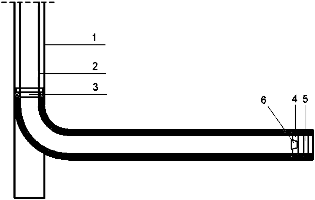
[0038] S1. Sidetrack drilling in the original casing 1, and then place the 3.5in tubing 2 with a suspension packer 3, floating hoop 4, and floating shoes 5 at predetermined positions;

[0039] S2. Set the hanging packer 3, squeeze the cement into the 3.5in tubing 2 to cement the well, throw the cementing plug 6 to touch and press to complete the well cementing, press and test;

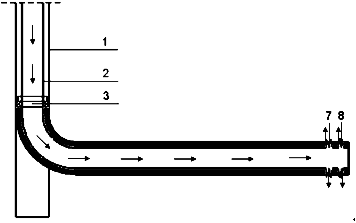
[0040] S3. After the pressure test, the floating hoop 4 dissolution control switch is opened by pressure, the floating hoop 4, the floating shoe 5, and the cementing rubber plug 6 are gradually dissolved. After the dissolution is completed, the first channel 7 is formed, and the 3.5in tubing 2 is injected into the fracturing Liquid, the first stage of fracturing construction;

[0041] S4. Enter the bridge injection tool string or hydraulic jet fracturing string through the cable 9, start the sett...

Embodiment 2

[0047] On the basis of Example 1, the dissolution time of the floating hoop, floating shoe, and cementing rubber plug is controllable and adjustable, and does not dissolve during the cementing period, meeting the cementing requirements. After the cementing is completed, the wellbore pressure test is carried out. Soluble tools dissolve quickly after pressure testing.

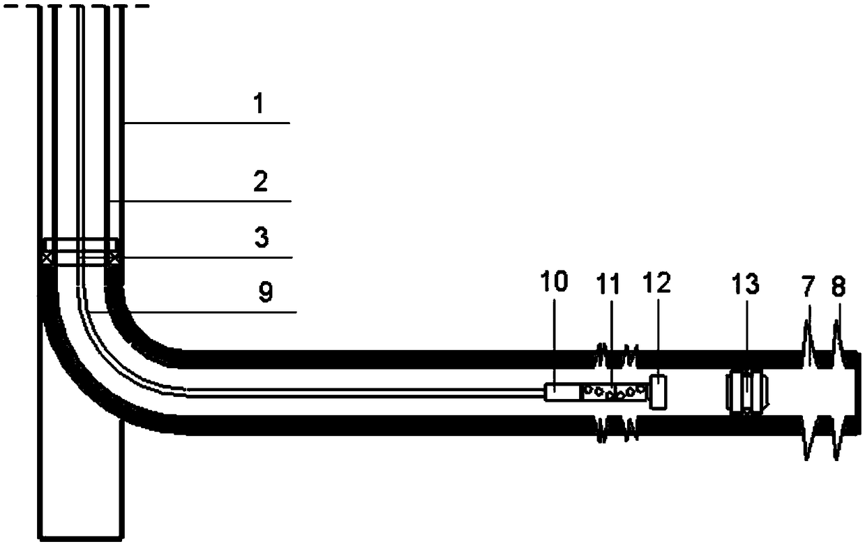
[0048] The bridge-shooting joint operation tool string is a bridle 10+magnetic positioning+ignition adapter+perforating gun 11+first setting tool 12+soluble bridge plug 13 connected sequentially from top to bottom, wherein the first setting Tool 12 is a fire setting tool or an electric setting tool.

[0049]When in step S4 the cable 9 is lowered into the bridge and used as a tool string, the operation method of the step S5 is as follows: lift the cable 9 so that the perforating gun 11 is located at the designed second-stage fracturing position, start the perforating gun 11, and ignite After perforating, the cabl...

Embodiment 3

[0053] A 3.5-inch sidetracking horizontal well staged fracturing method, comprising the following steps:

[0054] Such as figure 1 As shown, S1. Window sidetracking in 5.5in casing 1, 3.5in tubing 2 with hanging packer 3, floating hoop 4, and floating shoe 5 are placed at predetermined positions;

[0055] S2. Set the hanging packer 3, squeeze the cement into the 3.5in tubing 2 to cement the well, throw the cementing plug 6 to touch and press to complete the well cementing, press and test;

[0056] S3. The cementing is qualified, the pressure opens the dissolution control mechanism of the cementing rubber plug 6, the floating collar 4, and the floating shoe 5, the cementing rubber plug 6, the floating collar 4, and the floating shoe 5 start to dissolve, and the dissolution is completed, and the floating collar dissolution channel 7 is formed , floating shoe dissolving channel 8, such as figure 2 As shown; it is also possible to choose only the cementing rubber plug 6 and the...


PUM


Abstract

The invention discloses a 3.5-in side tracking horizontal well segmented fracturing method. The 3.5-in side tracking horizontal well segmented fracturing method comprises the steps that S1, window sidetrack drilling is conducted in an original casing, and a 3.5-in oil tube carries a suspension packer, a floating hoop and a floating shoe to be lowered to the predetermined position; S2, the suspension packer is set, cement is injected in a squeezed mode for well cementation, a well cementation rubber plug is put to conduct pressure bumping to complete well cementation, and pressurizing and pressure testing are conducted; S3, the floating hoop is started through pressure to dissolve a control switch, the floating hoop, the floating shoe and the well cementation rubber plug are gradually dissolved to form a first segment of channel, fracturing liquid is injected into the 3.5-in oil tube, and the first segment is subjected to fracturing construction; S4, a cable is lowered into a bridge perforation interaction tool string or a hydraulic jet fracturing pipe string, a setting tool is started, a soluble bridge plug is pushed to be set, and after setting is completed, the soluble bridge plug is released; S5, the cable is upwards lifted to the second segment of perforation position, perforation operation is conducted, and after perforation, the second segment is subjected to fracturing construction; S6, the step S4 and the step S5 are circulated, and fracturing construction of other layer segments is sequentially completed; and S7, the 3.5-in oil tube is rotated, the suspension packer is released, the upper 3.5-in oil tube is lifted out, and a pump is lowered for production. The fracturing method is small in risk, high in efficiency and reliable in packing.

Description

technical field [0001] The invention belongs to the technical field of oil and gas field development, and in particular relates to a staged fracturing method for a 3.5-inch sidetracked horizontal well. technical background [0002] The sidetracking process technology refers to opening a window in a certain place of the casing in the old wellbore, sidetracking a certain distance to form a new wellbore completion, and restoring the oil well to production. It can make full use of the original wellbore, ground facilities and Manifold system. It has the characteristics of strong targeting, low risk, short cycle, quick effect and low cost. With the prolongation of oilfield development time, casing damaged wells, water flooded wells and long shutdown wells are gradually increasing. The use of old wellbore for window sidetracking has become an important method to control casing damage wells, resume production of long shutdown wells, and tap the remaining oil potential. means. [...

Claims


Application Information

Patent Timeline
Patent Type & Authority Applications(China)
IPC IPC(8): E21B43/267
CPCE21B43/261E21B43/267
Inventor 任勇冯长青张矿生齐银蒙鑫赵粉霞刘忠能赵广民何华
Owner PETROCHINA CO LTD
Learn More