Loop type heat pipe

A loop pipe and heat pipe technology, applied in the field of loop type heat pipes, can solve the problems of unable to assist heat dissipation, overheating of loop type heat pipes, and difficult to control the direction.

Pending Publication Date: 2019-03-01
泽鸿(广州)电子科技有限公司
View PDF0 Cites 2 Cited by
  • Summary
  • Abstract
  • Description
  • Claims
  • Application Information

AI Technical Summary

Problems solved by technology

However, a disadvantage of the traditional loop heat pipe is that when the water-cooled liquid in the heated cavity changes from a liquid state to a gaseous state when heated, the gaseous water-cooled liquid is not easy to be controlled, and may continue to flow to one side of the heated cavity. counter flow
[0004] In addition, another disadvantage of the traditional loop heat pipe is

Method used


Image

  • Loop type heat pipe
  • Loop type heat pipe
  • Loop type heat pipe

Examples


Embodiment Construction

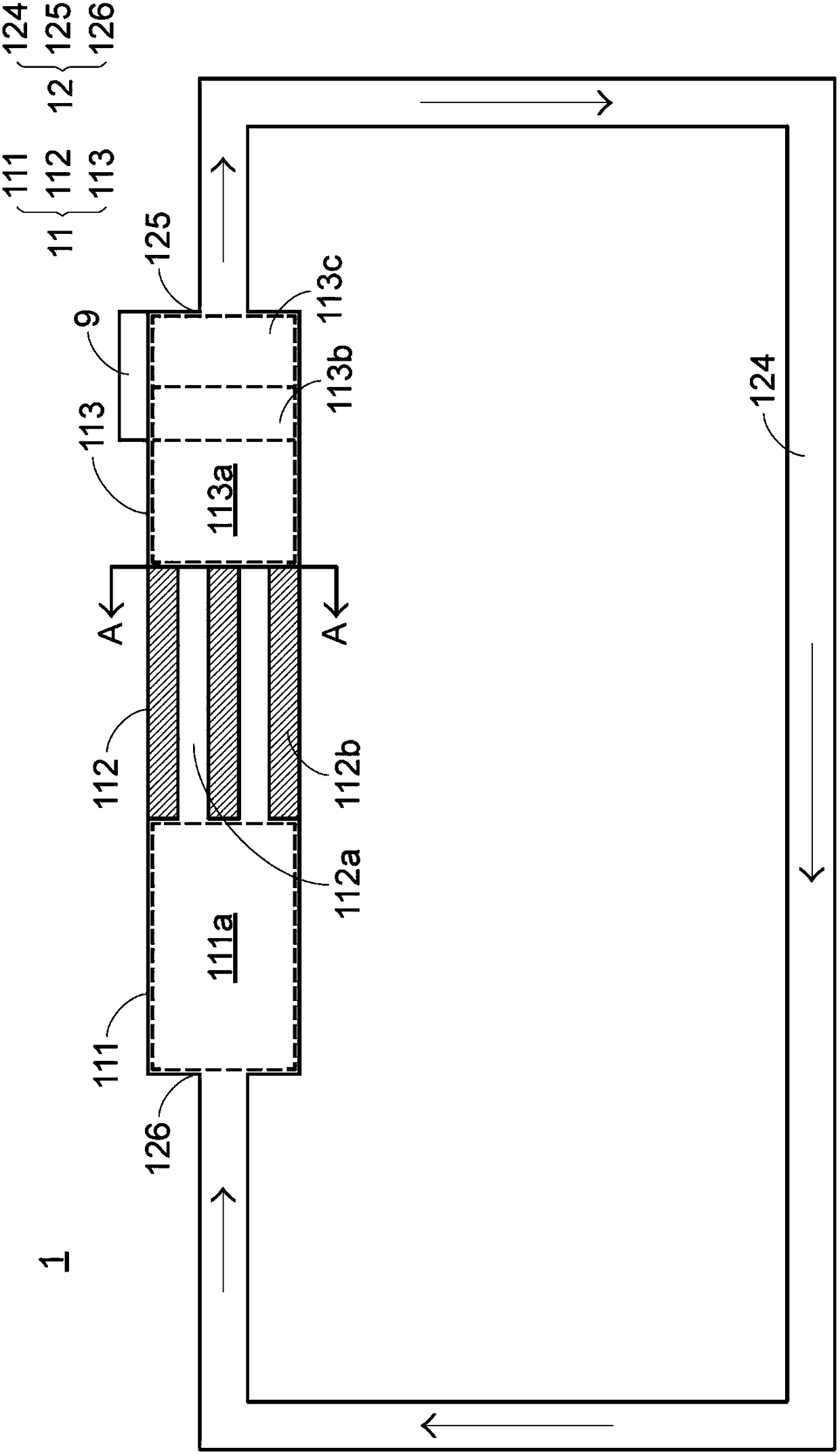
[0019] Please see first figure 1 , figure 1 It is a schematic top view of the first embodiment of the loop heat pipe of the present invention. The loop-type heat pipe 1 of the present invention can be configured in most electronic equipments to reduce the operating temperature of the electronic components (hereinafter referred to as a heat source 9 ) of the electronic equipments. Preferably, the loop-type heat pipe 1 is attached to the heat source 9 to absorb part of the heat from the heat source 9 . The loop-type heat pipe 1 of the present invention includes an evaporation cavity 11 and a loop tube body 12. The loop tube body 12 has a tube body 124, an inlet nozzle 125 and an outlet nozzle 126, and the loop tube body 12 is connected to the evaporation cavity body 11. , wherein an outlet of the evaporation chamber 11 is connected to the inflow nozzle 125 of the return pipe 12 , and an inlet of the evaporation chamber 11 is connected to the outlet 126 of the return pipe 12 . ...


PUM


Abstract

The invention provides a loop type heat pipe. The loop type heat pipe comprises a loop pipe body and an evaporation cavity, wherein the evaporation cavity comprises a first containing chamber, a second containing chamber and a third containing chamber, the first containing chamber, the second containing chamber and the third containing chamber communicate with one another, the first containing chamber comprises a first liquid storage area, the second containing chamber comprises at least one backflow prevention flow channel, the third containing chamber comprises a second liquid storage area,and the third containing chamber is in contact with a heat source of the outside; and the first liquid storage area and the second liquid storage area are arranged so that water cooling liquid in thesecond liquid storage area can be rapidly and completely consumed, the water cooling liquid in the first liquid storage area can flow to the second liquid storage area to be used as adjustment. According to the loop type heat pipe, the back flowing of the water cooling liquid can be avoided, and air burning of a heated cavity can be prevented.

Description

technical field [0001] The present invention relates to a loop-type heat pipe, in particular to a loop-type heat pipe with a compensation chamber additionally storing water-cooling liquid. Background technique [0002] With the rapid development of computers and various electronic products, the convenience brought by them has made modern people develop the habit of using them for a long time, but the heat generated by computers and various electronic products during long-term operation The disadvantage of not being able to disperse in time accordingly also comes with it. So the loop heat pipe was born accordingly. [0003] The traditional loop heat pipe has a heating cavity and a pipeline connected to the heating cavity. The heating cavity and the pipeline together define a loop flow channel, and the water-cooling liquid flows in the loop flow channel. Ideally, the water-cooled liquid in the heated cavity advances toward an outlet of the heated cavity along a specific circ...

Claims


Application Information

Patent Timeline
IPC IPC(8): F28D15/02
CPCF28D15/0266
Inventor 吴安智陈志伟
Owner 泽鸿(广州)电子科技有限公司
Why Eureka
Try Eureka