
A radio frequency signal shielding circuit and a shielding card

A technology of radio frequency signals and shielding circuits, applied in electromagnetic radiation induction, record carriers used by machines, instruments, etc., can solve problems such as theft of bank card funds

Active Publication Date: 2019-03-01
湖北用芯物联科技有限公司
View PDF7 Cites 0 Cited by
  • Summary
  • Abstract
  • Description
  • Claims
  • Application Information

AI Technical Summary

Problems solved by technology

Therefore, when carrying a physical chip bank card with you, it is easy for the read-write device to emit radio frequency information to steal the funds in the bank card by the secret-free payment method, so there is a certain risk of the card being stolen

Method used


Image

  • A radio frequency signal shielding circuit and a shielding card
  • A radio frequency signal shielding circuit and a shielding card

Examples


Embodiment Construction

[0020] In order to more clearly illustrate the technical solution of the present invention, the claims of the present invention will be further described in detail below in conjunction with specific embodiments and drawings. It can be understood that the following drawings only show some embodiments of the present invention, so It should not be regarded as a limitation on the scope, and any limited number of modifications made by anyone within the scope of the claims of the present invention are still within the scope of the claims of the present invention.

[0021] It should be understood that, in the description of the present invention, it should be explained that the orientation or positional relationship indicated by the terms "upper", "lower" and so on is based on the orientation or positional relationship shown in the drawings, or the orientation or positional relationship indicated by the product of the invention. Orientation or positional relationship that is conventio...


PUM


Abstract

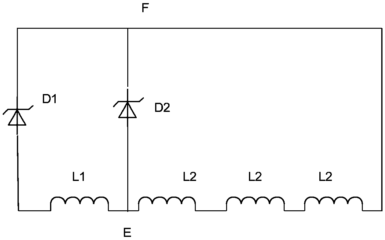
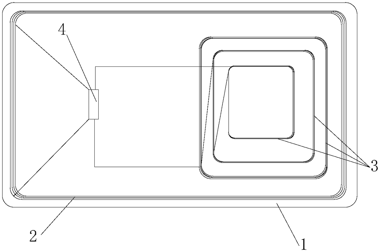
A radio frequency signal shielding circuit includes a first inductor and a second inductor. At one end of that first voltage stabilize tube and the second voltage stabilizing tube. A first common contact is arranged between the first inductor and the positive electrode of the second voltage stabilizer tube, two negative electrodes of the first voltage stabilizer tube and the second voltage stabilizer tube are connected to form a second common contact, and the first common contact and the second common contact are respectively connected with both ends of the second inductor, wherein the secondinductor value is larger than the first inductor. When in use, the first inductor obtains energy, and the second inductor boosts the circuit. When the voltage of the first inductor is greater than thereverse breakdown voltage of the voltage stabilizer, the first inductor is short-circuited so that no electric energy can be obtained, and the voltage stabilizer conducts forward. The first inductorobtains electrical energy, and the second inductor boosts to the reverse breakdown of the voltage stabilizer, then the first inductor loses electrical energy, and the voltage stabilizer is continuously turned off and on during the reading process, and the first inductor generates electromagnetic wave to interfere with the reading and writing RF signals. The invention can be widely used in the interference of frequency-emitted read-write signals.

Description

technical field [0001] The invention relates to the technical field of smart chips, in particular to a radio frequency signal shielding circuit and a shielding card. Background technique [0002] Existing smart chip cards have been widely used on bank cards, such as credit cards, due to their higher security than magnetic stripe cards, which can prevent being copied and have higher security. In order to facilitate the use of users, banks usually have a certain amount of password-free payment function for chip bank cards. Because the chip bank card can usually be swiped in two ways, one is the contact type, after the chip bank card is in contact with the reading and writing device. Read the corresponding information or transaction; the other is through non-contact, when the chip bank card is placed within the reading and writing range of the reading and writing device, the corresponding information or transaction can be read without contact. Therefore, when carrying a physic...

Claims


Application Information

Patent Timeline
Patent Type & Authority Applications(China)
IPC IPC(8): G06K7/10G06K19/073
CPCG06K7/10257G06K19/07318
Inventor 兰荣
Owner 湖北用芯物联科技有限公司
Learn More