Locking grounding clamp

A technology of grounding clips and fixtures, which is applied in the direction of connection, conductive connection, and wire-wound connectors, and can solve problems such as exposure of technicians and electric shock of technicians

Inactive Publication Date: 2019-03-01
QUANTA ASSOC
View PDF4 Cites 6 Cited by
  • Summary
  • Abstract
  • Description
  • Claims
  • Application Information

AI Technical Summary

Problems solved by technology

This could expose the mechanic to a voltage potential and...

Method used


Image

  • Locking grounding clamp
  • Locking grounding clamp
  • Locking grounding clamp

Examples


Embodiment Construction

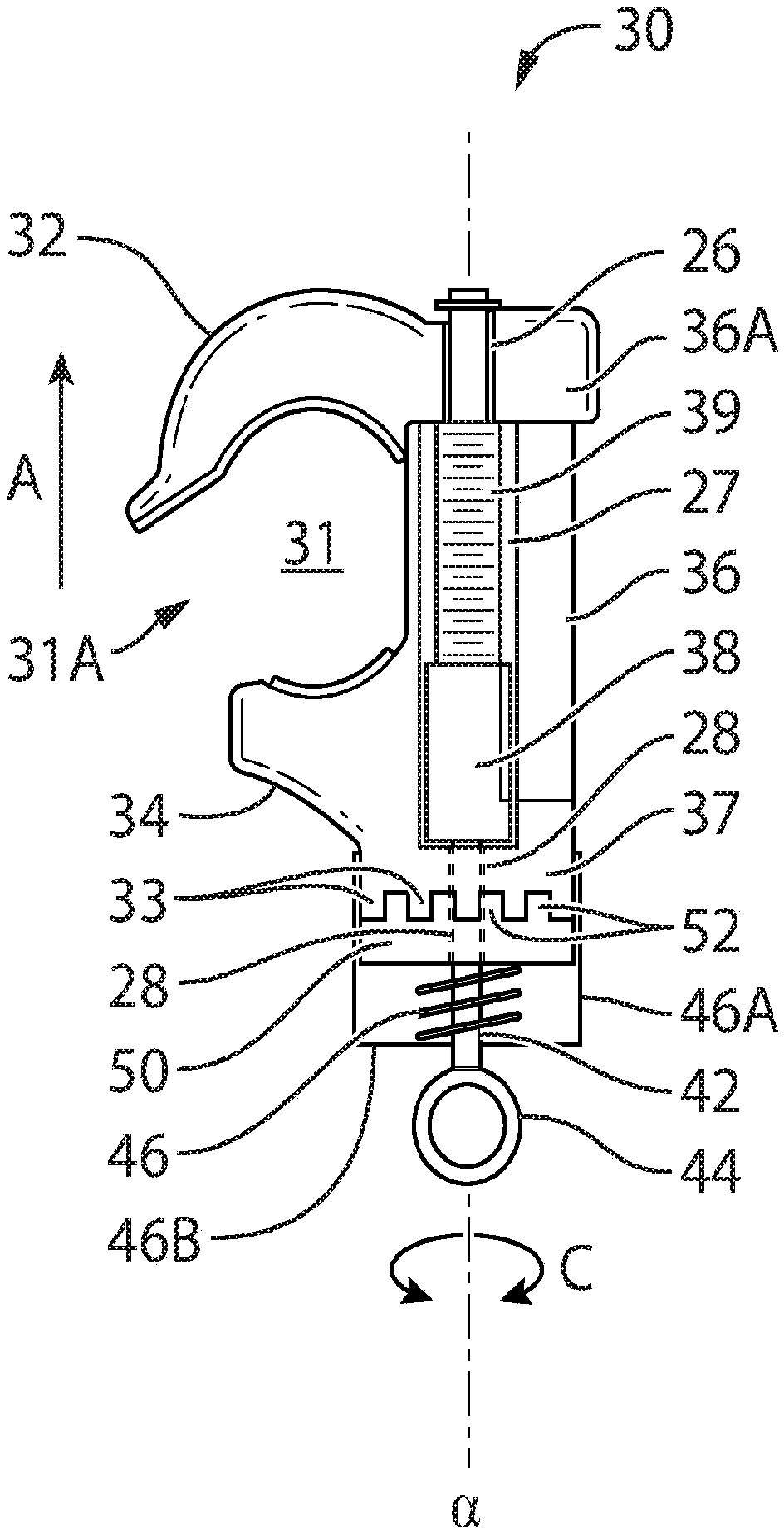
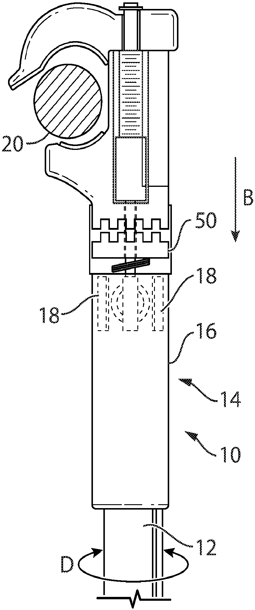
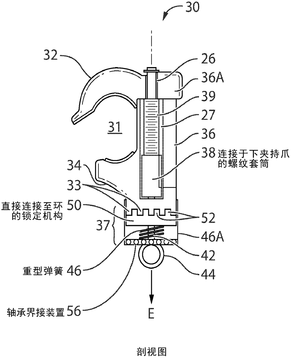
[0016] In an embodiment of the present disclosure, the locking ground clamp 30 includes a frame 36 that supports a clamping member 34 . The frame includes clamping members 32 at opposite ends of the frame. The clamping member and the frame define between them a capture chamber 31 having an opening 31A. Capture chamber 31 is dimensioned to receive via opening 31A such as figure 2 Conductor 20 shown in cross-section. Advantageously, the capture cavity 31 conforms in shape to the conductor 20 so as to enclose this conductor 20 .

[0017] A square shaft 42 is supported on or within the frame 36 and is disposed alongside the clamping member 34 . A square shaft 42 (square in cross section) is inserted through the opening 26 at the upper end 36A of the frame 36 through a channel or cutout 27 running along the frame 36 and through an opening 28 in the locking portion 37 of the frame 36 . A ferrous locking ring 50 is mounted adjacent to this portion 37 . The square shaft 42 is jo...


PUM


Abstract

A grounding clamp includes a safety lock-out which locks the operation of the clamp in the absence of a hot-stick. A clamping member cooperates with a frame having an arm, and is selectively biasableby a user to translate the clamping member relative to the frame to clamp a conductor between the clamping member and arm. The lock-out cooperates with the clamping member to prevent the translation of the clamping member unless in the presence of an insulating tool such as a hot-stick.

Description

technical field [0001] The present disclosure generally relates to the field of grounding clamps for grounding high voltage conductors. More specifically, the present disclosure relates to grounding clamps having locks actuatable by use of an insulated wire tool. Background technique [0002] Electricians use grounding cables almost every day in the industry to help manage dangerous voltages and currents in out-of-power power lines and electrical installations. Groundings are designed to be installed and removed using insulated tools, such as those known as Grip-Allsticks or Shotguns, to keep mechanics a safe distance from the hazard area. [0003] When installing a ground, always make the earliest connection to the ground point. A tradesman will usually make this connection by hand rather than with insulated tools because there is no hazardous energy present to make this connection. [0004] Whenever making connections to conductors or equipment that may be at a differen...

Claims


Application Information

Patent Timeline
IPC IPC(8): H01R11/15
CPCH01R43/002H01R11/15H02G1/02H01R11/14H01R43/00H01R43/22
Inventor P·H·夸德夫利格D·K·瓦布内格尔J·C·托特D·N·奥康奈尔
Owner QUANTA ASSOC
Why Eureka
Try Eureka