Covered stent
A covered stent and covering technology, applied in stents, medical science, blood vessels, etc., can solve the problems of compressing branch blood vessels, poor compatibility, and large stress in the connecting section, achieving good universality, simple structure, and avoiding channel closure. Effect
- Summary
- Abstract
- Description
- Claims
- Application Information
AI Technical Summary
Problems solved by technology
Method used
Image
Examples
no. 1 example
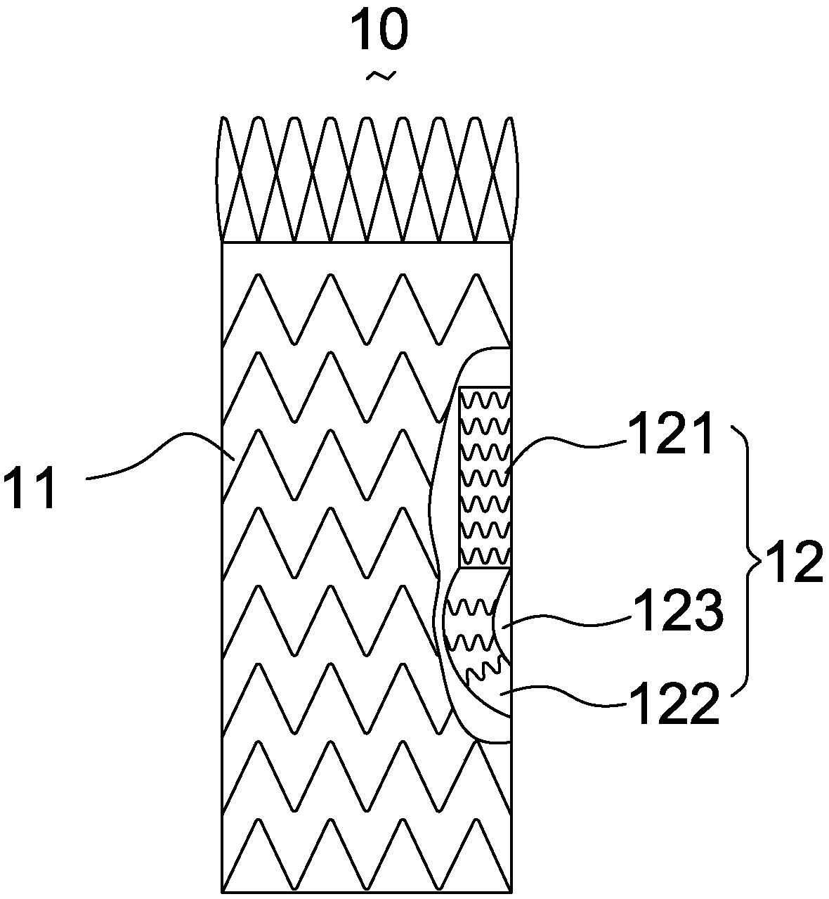
[0045] like Figure 5 As shown, the support 124 of the free section 122 includes a plurality of wave-shaped rings 1241 arranged at intervals along its generatrix. In this embodiment, the waveform phases of the wave-shaped rings 1241 are the same. In other possible embodiments, the waveform phases of the multiple waveform rings can also be reversed. like Image 6 As shown, a plurality of undulating rings 1241 are connected to the membrane of the free segment 122 by sutures 1242 only at their crests and / or troughs. The advantage of being connected to the film only at the position of the peak and / or valley is that it can avoid the closure of the free section channel and keep the flexibility of the free section 122 to the greatest extent, because the contact between the support 124 and the film is minimized. When the free segment is axially compressed, the coating can be compressed to the maximum and the deformation becomes free. Not all peaks and troughs need to be attached to...
no. 2 example
[0047] like Figure 7 As shown, the bracket 125 of the free section 122 includes a plurality of wave-shaped rings 1251, the waveform phases of two adjacent wave-shaped rings 1251 are opposite, and the peaks and troughs of two adjacent wave-shaped rings 1251 are interlocked. . The interlock setting mentioned in the present invention refers to such as Figure 8 shown in the structure, Figure 7 In the second wave-shaped ring 1251, the metal wire that forms the crest part begins with Figure 7 The first wave-shaped ring 1251 passes over the metal wire forming the trough part, and then passes under the metal wire forming the trough part. Using this interlocking structure to connect two adjacent wave-shaped rings instead of connecting them through sutures can reduce the number of fixed points, and this interlocking structure makes the connection between two adjacent wave-shaped rings 1251 The space between them can be stretched and fine-tuned in the axial direction, which is co...
no. 3 example
[0050] like Figure 10 As shown, on the basis of the interlocking arrangement of any two adjacent wave-shaped rings in the previous embodiment, the bracket 126 of the free section in this embodiment includes a first wave-shaped ring 1261, a second wave-shaped ring 1262 and a third wave-shaped ring 1263 located between the first wave-shaped ring 1261 and the second wave-shaped ring 1262 . The third waveform ring 1263 has waveforms of unequal heights. Wherein, the third wave-shaped ring 1263 includes a plurality of first peaks 1263a close to the first wave-shaped ring 1261 and a plurality of second peaks 1263b away from the first wave-shaped ring 1261, the first wave peaks 1263a and the second wave peaks 1263b are arranged at intervals along the circumferential direction of the third wave-shaped ring 1263 . And the vertices of all the first crests 1263a fall on a plane perpendicular to the axis of the third wave-shaped ring 1263, and the vertices of all the second crests 1263b...
PUM
 Abstract
Description
Claims
Application Information
 - R&D
- Intellectual Property
- Life Sciences
- Materials
- Tech Scout
- Unparalleled Data Quality
- Higher Quality Content
- 60% Fewer Hallucinations
Browse by: Latest US Patents, China's latest patents, Technical Efficacy Thesaurus, Application Domain, Technology Topic, Popular Technical Reports.
© 2025 PatSnap. All rights reserved.Legal|Privacy policy|Modern Slavery Act Transparency Statement|Sitemap|About US| Contact US: help@patsnap.com


