Efficient coating dispersing machine

A technology for dispersing machines and coatings, applied in mixers, mixers with rotating stirring devices, dissolving, etc., can solve problems such as inability to obtain sufficient mixing and mixing, affect the working efficiency of coating dispersing machines, and low efficiency, and achieve improved cutting Efficiency, reduced work load, sufficient mixing effect

Pending Publication Date: 2019-03-05
TIANJIN SHENGXINLONG POWDER PAINT
View PDF5 Cites 0 Cited by
  • Summary
  • Abstract
  • Description
  • Claims
  • Application Information

AI Technical Summary

Problems solved by technology

The dispersing discs of the current paint dispersing machine are mostly dispersing discs with a simple structure, and the stirring efficiency is relatively low, and there are dead angles above or below the dispersing disc of the paint dispersing machine during work, and sufficient stirring and mixing cannot be obtained within a limited time. These all affect the working efficiency of the paint disperser

Method used


Image

  • Efficient coating dispersing machine
  • Efficient coating dispersing machine
  • Efficient coating dispersing machine

Examples


Embodiment 1

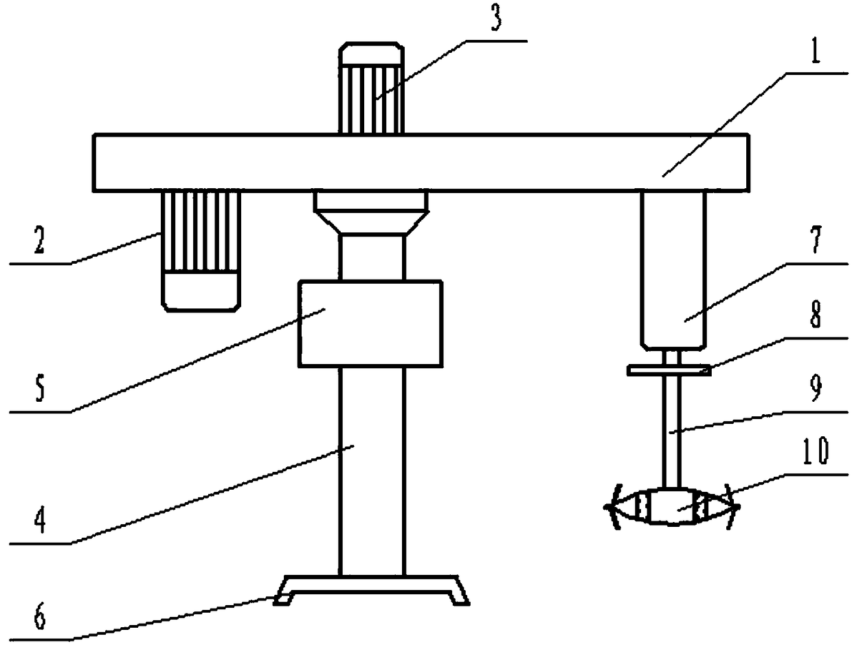
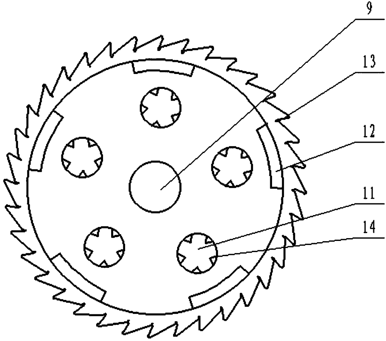
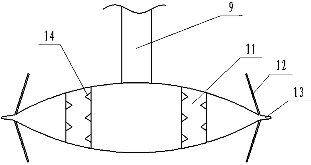
[0014] A high-efficiency paint dispersing machine, including a beam 1, a motor A2, a motor B3, a column 4, a controller 5, a base 6, a shaft seat 7, a flywheel 8, a dispersing shaft 9, a dispersing disc 10, a through hole 11, and a blocking cutting piece 12 , scattered teeth 13, wolf tooth protrusions 14, a motor B3 is arranged on the top of the crossbeam 1, a motor A2 is arranged at one end of the bottom of the crossbeam 1, a column 4 is provided at the middle part of the bottom of the crossbeam 1, a controller 5 is arranged on the column 4, and the bottom of the column 4 A base 6 is provided, and the other end of the beam 1 is provided with an axle seat 7, the lower end of the axle seat 7 is connected with the dispersing shaft 9, and a flywheel 8 is arranged on the dispersing shaft 9, and the bottom end of the dispersing shaft 9 is connected with the dispersing disc 10, and the upper end of the dispersing disc 10 A through hole 11 is opened, and the inner surface of the throu...

Embodiment 2

[0016] When the present invention is actually used, the dispersing disc 10 rotates to stir the slurry, the dispersing teeth 13 cut the slurry, the slurry flows up and down through the through hole 11, and the stirring effect is enhanced. When the slurry passes through the through hole 11, the wolf on the inner surface of the through hole 11 The tooth protrusion 14 cuts the slurry again, and the blocking cutting piece 12 bounces back the slurry impacted on its surface, so that the slurry accelerates to flow through the through hole 11, and the cutting efficiency of the wolf tooth protrusion 14 is improved. When the blocking cutting pieces 12 rotate, the slurry flowing through the blocking cutting pieces 12 is cut to speed up the slurry mixing efficiency. The flywheel 8 makes the high-speed dispersing shaft 9 rotate stably, and finally improves the service life of the dispersing machine.


PUM


Abstract

The invention discloses an efficient coating dispersing machine. The efficient coating dispersing machine is characterized by comprising a cross beam, a motor A, a motor B, a stand column, a controller, a base, a shaft seat, a flywheel, a dispersing shaft, a dispersing disc, through holes, blocking cutting pieces, dispersing teeth and spike projections. According to the efficient coating dispersing machine, the flywheel is additionally arranged, so that the dispersing shaft is more stable in high-speed operation, and the service life of the dispersing machine is prolonged. When the dispersingdisc rotates to stir slurry and the slurry is transversely cut by the dispersing teeth, due to the fact that the through holes are formed in the dispersing disc, the slurry flows up and down through the through holes when being stirred, so that the stirring effect is enhanced; the inner surface of each through hole is spirally provided with the spike projections for repeatedly cutting the slurry flowing into the through holes, and the blocking cutting pieces are used for rebounding and accelerating the slurry which is transversely flushed to the surface of the blocking cutting pieces to enablethe slurry to flow into the through holes, so that cutting efficiency of the spike projections is improved. The blocking cutting pieces are arranged at the edge of the dispersing disc at intervals, and are used for cutting the slurry among the blocking cutting pieces during high-speed rotation, and final stirring efficiency is improved.

Description

technical field [0001] The invention relates to the field of paint production equipment, in particular to a high-efficiency paint disperser. Background technique [0002] The paint disperser is mainly used for pulverizing, dispersing, emulsifying and mixing liquid raw materials with different viscosities and slurries. Through the high-speed operation of the upper and lower teeth of the dispersing disc, it is a new type of high-efficiency mixing equipment, which performs high-speed strong shearing, impact and pulverization of the materials. , Dispersion, to achieve the functions of rapid mixing, dissolution, dispersion and refinement. It is an efficient equipment for stirring, dispersing and dissolving solids such as coatings. The dispersing discs of the current paint dispersing machine are mostly dispersing discs with a simple structure, and the stirring efficiency is relatively low, and there are dead angles above or below the dispersing disc of the paint dispersing machin...

Claims


Application Information

Patent Timeline
IPC IPC(8): B01F7/26B01F27/93
CPCB01F27/074B01F27/1151B01F27/1152B01F27/191B01F27/93B01F2101/30
Inventor 李明水
Owner TIANJIN SHENGXINLONG POWDER PAINT
Why Eureka
Try Eureka