
Method and system for a boosted engine

A technology of engines and compressors, applied in combustion engines, engine control, engine components, etc., can solve problems such as slow boost response

Pending Publication Date: 2019-03-05
FORD GLOBAL TECH LLC
View PDF1 Cites 4 Cited by
  • Summary
  • Abstract
  • Description
  • Claims
  • Application Information

AI Technical Summary

Problems solved by technology

However, this can result in a slower boost response

Method used


Image

  • Method and system for a boosted engine
  • Method and system for a boosted engine
  • Method and system for a boosted engine

Examples


Embodiment Construction

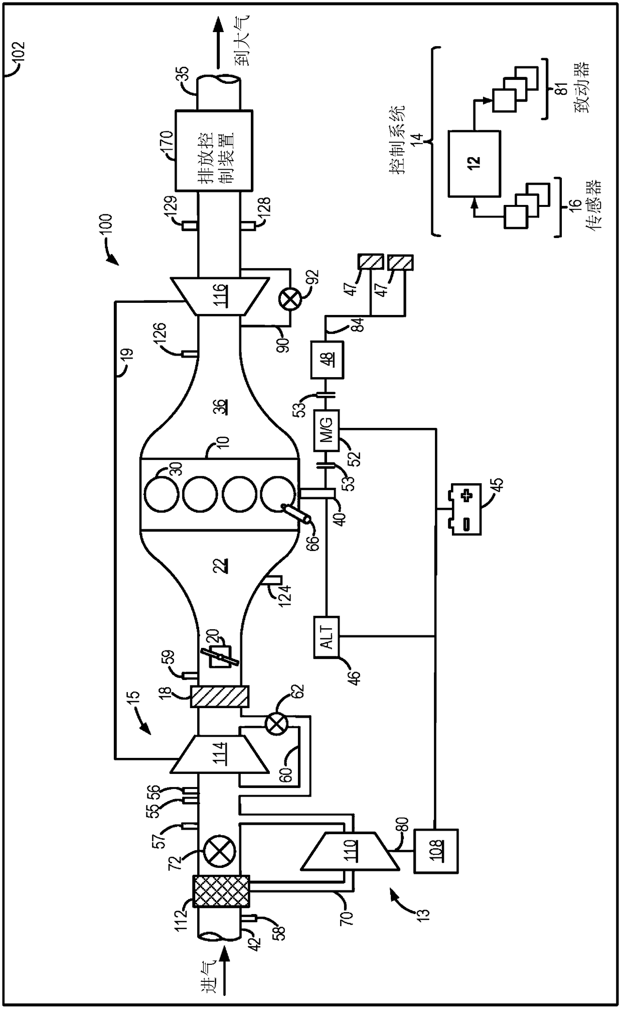
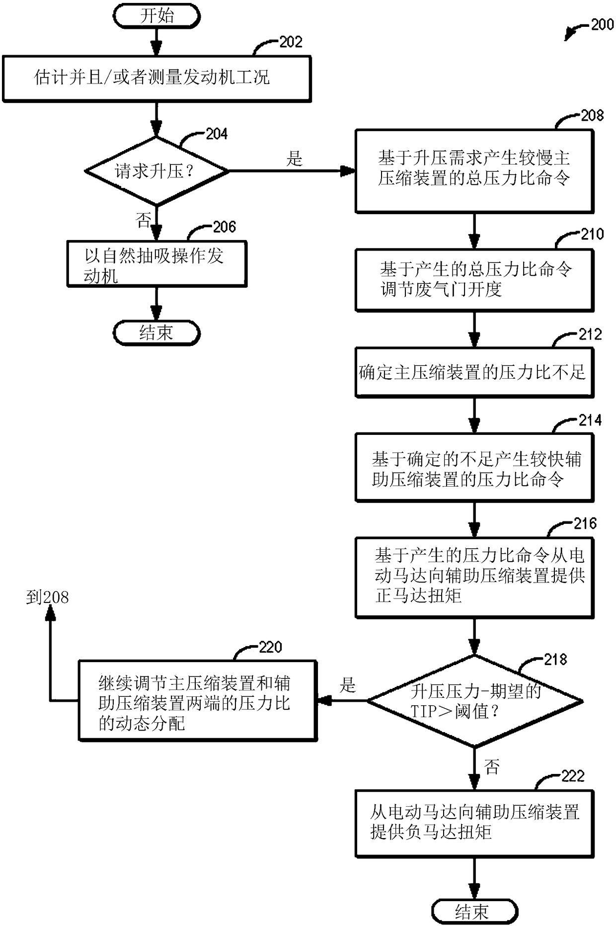
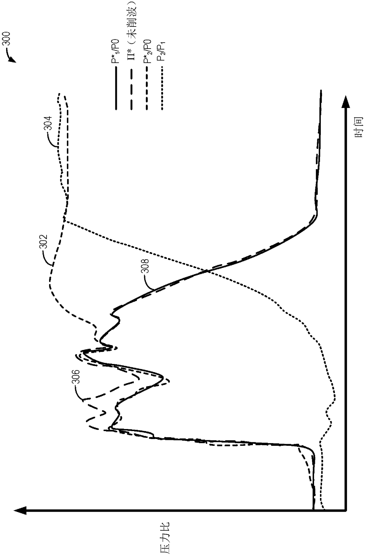
[0017] The following description relates to systems and methods for boost control in an engine system having stepped boost devices, where at least one of the boost devices is configured with electric assist. figure 1 A non-limiting example of such a boosted engine system is shown in , where the turbocharger is staged downstream of the electric supercharger. Boost control in compound boost systems can be achieved by dynamically assigning different pressure ratio commands to each compression device, and by further using lead compensation to reduce pressure overshoot. The engine controller can be configured to Figure 5 The control framework executes control programs such as figure 2 example program) to assign pressure ratios to slower acting compressors based on torque demand, while assigning pressure ratios to faster acting compressors (which have electric assist) based on airflow insufficiency. Additionally, the controller may use a lead compensator to determine when to inc...


PUM


Abstract

The invention relates to a method and a system for a boosted engine. Methods and systems are provided for coordinated control of a compound boosting system, including a first compressor staged upstream of a second compressor in an engine intake. In one example, a method may include operating the second, downstream compressor in steady-state to achieve an overall pressure ratio across the compoundboosting system while operating the first, upstream compressor transiently, based on an airflow shortfall at the downstream compressor. A timing and amount of electric assistance provided to transiently operate the first, upstream compressor may be adjusted dynamically as the pressure ratio across the second compressor changes.

Description

technical field [0001] The present description generally relates to methods and systems for boosted engine systems having staged boosting devices. Background technique [0002] Engines may be equipped with boosting devices, such as turbochargers or superchargers, to increase airflow into the combustion chambers. Turbochargers and superchargers use an intake compressor to compress the intake air entering the engine. A turbocharger includes a compressor mechanically driven by an exhaust turbine, while an electric supercharger includes a compressor electrically driven by a motor. In certain engine systems, one or more intake boost devices may be staged in series or parallel in what may be referred to as a compound boost configuration. For example, a fast auxiliary boost device (eg, an electric supercharger) may be utilized to increase the transient performance of a slower main boost device (eg, a turbocharger). In such configurations, the size of the turbocharger may be incr...

Claims


Application Information

Patent Timeline
Patent Type & Authority Applications(China)
IPC IPC(8): F02B37/04F02B37/12F02B37/18F02D41/00
CPCF02B37/04F02B37/12F02B37/183F02D41/0007F02D2200/04F02B37/16F02B37/186F02B39/10F02B39/16F02D11/105F02D41/10F02D2200/0402F02D2200/602Y02T10/12F02D11/02F02D41/26
Inventor 肖柏韬D·贝尔T·凯利T·斯道尔森菲尔德J·H·巴克兰
Owner FORD GLOBAL TECH LLC
Learn More