Method of setting-up steady state model of VSC-based multi-terminal HVDC transmission system

a multi-terminal, high-voltage direct current technology, applied in the direction of electrical power transfer ac network, complex mathematical operations, instruments, etc., can solve the problem of not being suitable for configuration of multi-terminal hvdc transmission system, and achieve the effect of reducing the complexity of computational analysis

Inactive Publication Date: 2006-12-14
CHANG GUNG UNIVERSITY
View PDF0 Cites 132 Cited by
  • Summary
  • Abstract
  • Description
  • Claims
  • Application Information

AI Technical Summary

Benefits of technology

[0018] To achieve the objective, the present invention intends to provide a method of setting-up a steady state model of VSC-based Multi-terminal high-voltage DC (referred to as M-VSC-HVDC) suitable for analysis of power flow of large power system. When...

Problems solved by technology

However, it's not suitable for configuration of Multi-terminal HVDC transmission syst...

Method used


Image

  • Method of setting-up steady state model of VSC-based multi-terminal HVDC transmission system
  • Method of setting-up steady state model of VSC-based multi-terminal HVDC transmission system
  • Method of setting-up steady state model of VSC-based multi-terminal HVDC transmission system

Examples


Embodiment Construction

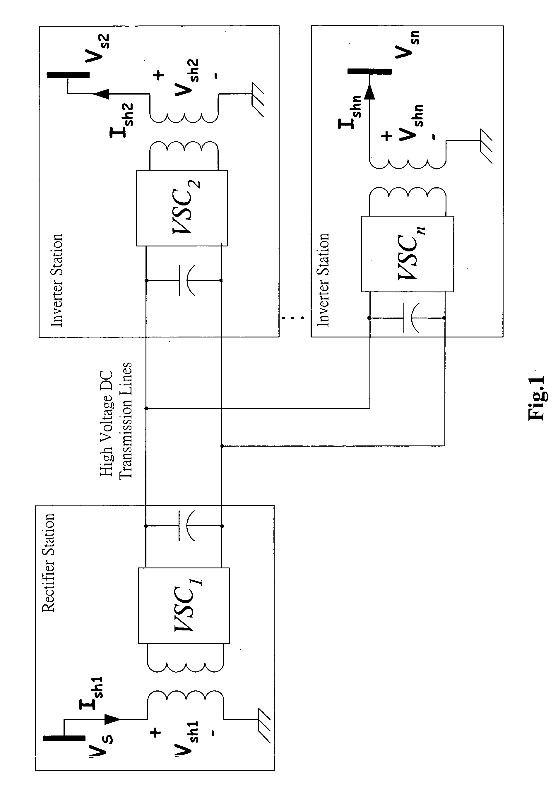
[0027] According to HVDC system in power industry, some electricity / electronics technologies are used to receive active power of AC power grid at rectifier end, convert ACV into DCV, and then transmit to converter end via DC transmission line, where DC is converted into AC and fed to AC power grid. With the help of HVDC transmission system, active power through DC transmission line can be controlled in an accurate and rapid manner.

[0028] In addition, input reactive power at terminals of HVDC transmission system can be independently controlled using its own DC capacitors. Therefore, HVDC transmission system is often used to improve the performance and efficiency of AC power grid.

[0029] However, HVDC steady state model for power flow analysis requires a basic and important task. Moreover, planning engineers of power system evaluate the impact of HVDC transmission system upon bus voltage and flow distribution of transmission line based on analysis of power flow.

[0030] Despite of num...


PUM


Abstract

The power flow model of the multiterminal voltage-source converter-based high voltage DC (M-VSC-HVDC) transmission system for large-scale power systems is studied. The mathematical model is derived using the d-q axis decomposition of HVDC's control parameter. The developed model can be applied to all existing shunt voltage-source converter (VSC) based controllers, including Static Synchronous Compensator (STATCOM), point-to-point HVDC system, back-to-back HVDC system and multiterminal HVDC system. A unified procedure is developed for incorporating the proposed model into the conventional Newton-Raphson power flow solver. The IEEE 300-bus test system embedded with multiple HVDC transmission systems under different configurations are investigated. Simulation results reveal that the proposed model is effective and accuracy in meeting various control objectives.

Description

BACKGROUND OF THE INVENTION [0001] 1. Field of the Invention [0002] The present invention relates generally to a steady state model of a multi-terminal high-voltage direct current based on voltage source converter (VSC) (referred to as M-VSC-HVDC), and more particularly to an improved one that can be applied for analysis of power flow of large power system. And, the voltage phasor / current vector relating to control parameters of HVDC transmission system and voltage source converter (VSC) are decomposed into direct-axis components and quadrature-axis components for further derivation. [0003] 2. Description of Related Art [0004] Electricity / electronics technology was firstly applied to control of power system at 1970s, one example of which is HVDC transmission system; [0005] HVDC transmission system was developed by Y. H. Song and A. T. Johns in Flexible AC Transmission Systems (FACTS) (vol. 30. London, United Kingdom: The Institution of Electrical Engineers, 1999). [0006] In general,...

Claims


Application Information

Patent Timeline
IPC IPC(8): G06F17/10
CPCH02J3/36Y02E60/60Y02E40/16Y02E40/10
Inventor CHU, CHIA-CHILEE, SHENG-HUEITSAI, HUNG-CHI
Owner CHANG GUNG UNIVERSITY
Why Eureka
Try Eureka