
Sequence valve

A sequence valve and valve body technology, applied in the field of hydraulic machinery, can solve the problems of increasing pipeline leakage, increasing operating time and labor intensity, and achieving the effect of reducing the risk of leakage, reducing installation time and labor intensity

Pending Publication Date: 2019-03-05
PETROCHINA CO LTD
View PDF9 Cites 1 Cited by
  • Summary
  • Abstract
  • Description
  • Claims
  • Application Information

AI Technical Summary

Problems solved by technology

[0005] Since the one-way sequence valve has the characteristics of smooth reverse and no pressure difference, when controlling multiple hydraulic cylinders to lift and reset in sequence, one-way sequence valves need to be connected in series in the forward and reverse directions of the pipeline, which not only increases the The risk of pipeline leakage, but also increased operating time and labor intensity

Method used


Image

  • Sequence valve
  • Sequence valve
  • Sequence valve

Examples


Embodiment Construction

[0067] In order to make the object, technical solution and advantages of the present invention clearer, the implementation manner of the present invention will be further described in detail below in conjunction with the accompanying drawings.

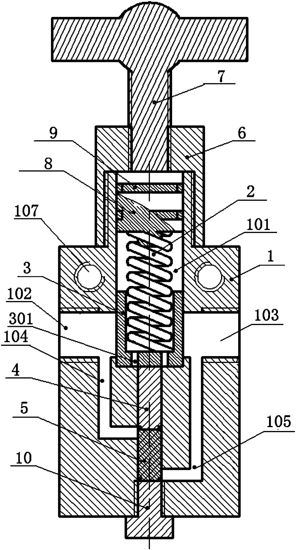
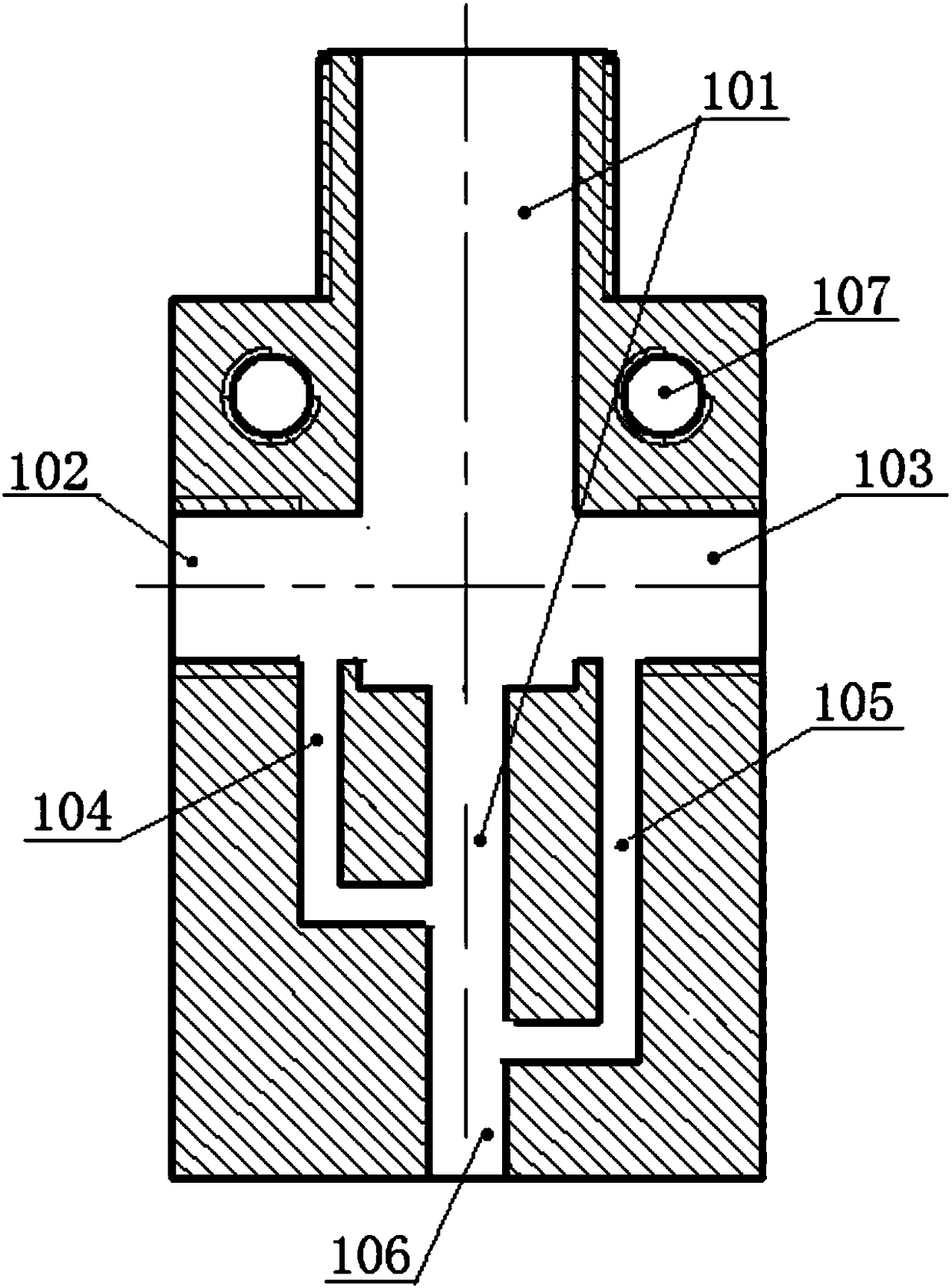
[0068] The embodiment of the present invention provides a sequence valve, such as figure 1 As shown, the sequence valve includes: a valve body 1 with a first cavity 101 along the axial direction, a spring 2 that is offset from top to bottom and arranged in the first cavity 101, a plunger 3 for breaking, a second One unlatching plunger 4, the second unlatching plunger 5. Further, see figure 2 , the left and right side walls of the valve body 1 are respectively provided with a first oil port 102 and a second oil port 103 communicating with the first cavity 101; the spring 2 is always in a compressed state; The inner wall of the first cavity 101 dynamically seals and slides, and is used to block and connect the first oil outlet 102 and...


PUM


Abstract

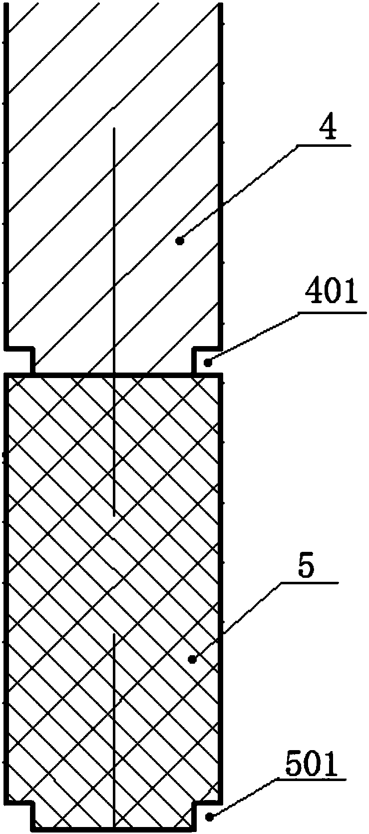
The invention discloses a sequence valve, and belongs to the field of hydraulic machinery. The sequence valve comprises a valve body with a first cavity in an axial direction, springs which are arranged in the first cavity in sequence from top to bottom and abutted against one another, a plunger used for connecting and disconnecting, a first opening plunger and a second opening plunger. The left side wall of the valve body and the right side wall of the valve body are each provided with a first oil passing opening and a second oil passing opening which are communicated with the first cavity. The springs are always in a compression state. The plunger used for connecting and disconnecting can slide along the inner wall of the first cavity in a sealing mode, and is used for blocking and communicating the first oil passing opening and the second oil passing opening. A first annular groove is arranged in the outer wall of the lower end of the first opening plunger, the first annular grooveis communicated with the first oil passing opening through a first passage arranged on the valve body. A second annular groove is arranged in the outer wall of the lower end of the second opening plunger, and the second annular groove is communicated with the second oil passing opening through a second passage arranged on the valve body. The first opening plunger and the second opening plunger canslide along the inner wall of the first cavity in a sealing mode.

Description

technical field [0001] The invention relates to the field of hydraulic machinery, in particular to a sequence valve. Background technique [0002] The sequence valve is a kind of pressure control valve. Its main function is to use the pressure as the control signal to automatically connect or cut off a certain oil circuit under the action of a certain control pressure. With the rapid development of science and technology, petroleum machinery, petroleum equipment and other industries use hydraulic control technology to carry out difficult and high-precision operations. Among them, the hydraulic cylinder is an essential device for implementing hydraulic control technology. When hydraulic control technology is used to carry out a job, usually multiple hydraulic cylinders are required to cooperate with each other, wherein each hydraulic cylinder is assigned a different task and operates in a certain sequence. At present, pipelines are usually connected between adjacent hydraul...

Claims


Application Information

Patent Timeline
Patent Type & Authority Applications(China)
IPC IPC(8): F15B13/07
CPCF15B13/07
Inventor 黄树孙连会王铁锋吕凤滨杨振涛陈辉李伟昂王延军盖伟兵
Owner PETROCHINA CO LTD
Learn More