
Combustion chamber structure and gas water heater

A technology of gas water heaters and combustion chambers, applied in fluid heaters, lighting and heating equipment, etc., can solve the problem of low preheating efficiency of catalytic combustion modules, and achieve the effect of improving preheating efficiency and speed

Pending Publication Date: 2019-03-05
WUHU MIDEA KITCHEN & BATH APPLIANCES MFG CO LTD +2
View PDF0 Cites 1 Cited by
  • Summary
  • Abstract
  • Description
  • Claims
  • Application Information

AI Technical Summary

Problems solved by technology

[0003] The main purpose of the present invention is to propose a combustion chamber structure aimed at solving the technical problem of low preheating efficiency of the catalytic combustion module in the combustion chamber of the prior art

Method used


Image

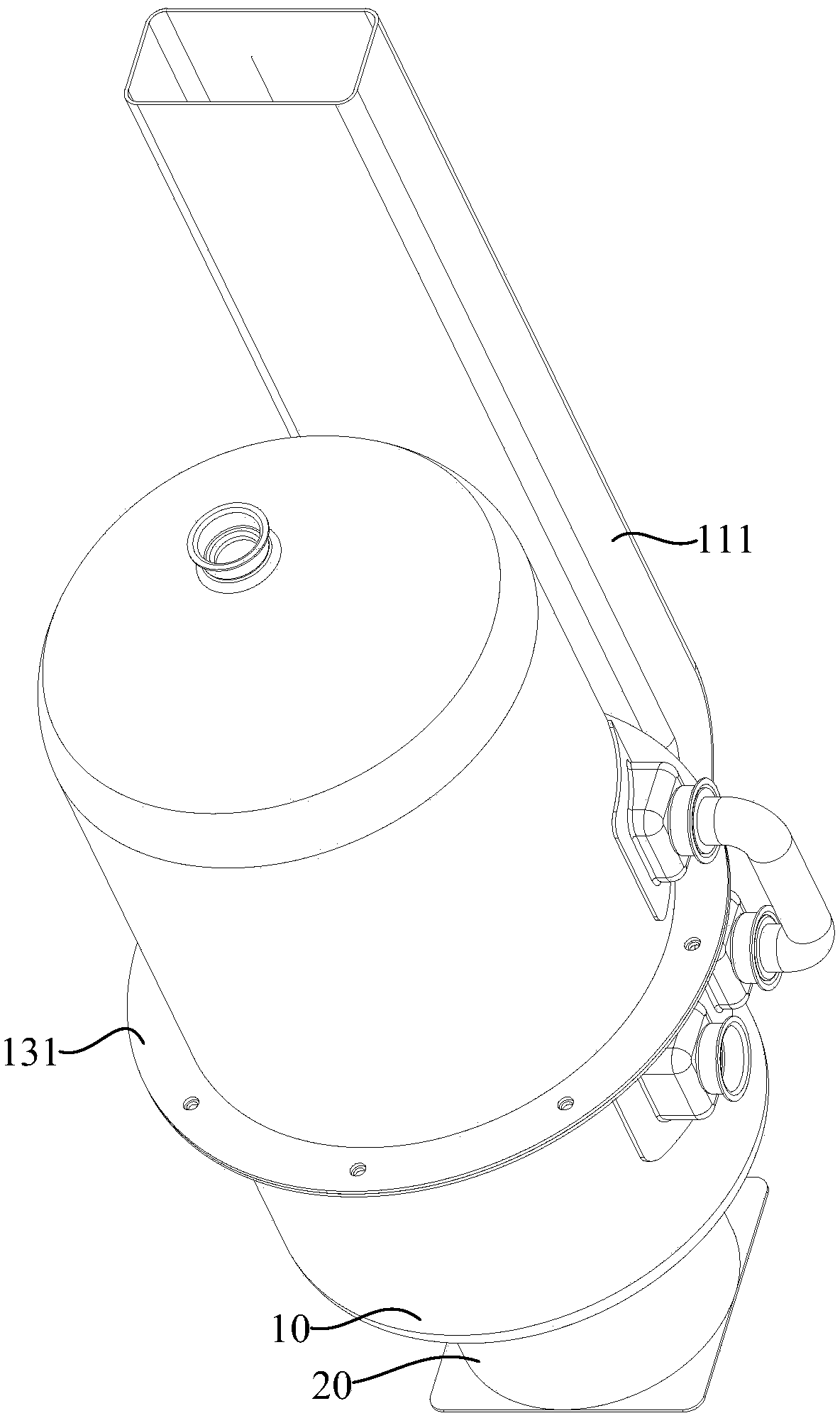
  • Combustion chamber structure and gas water heater
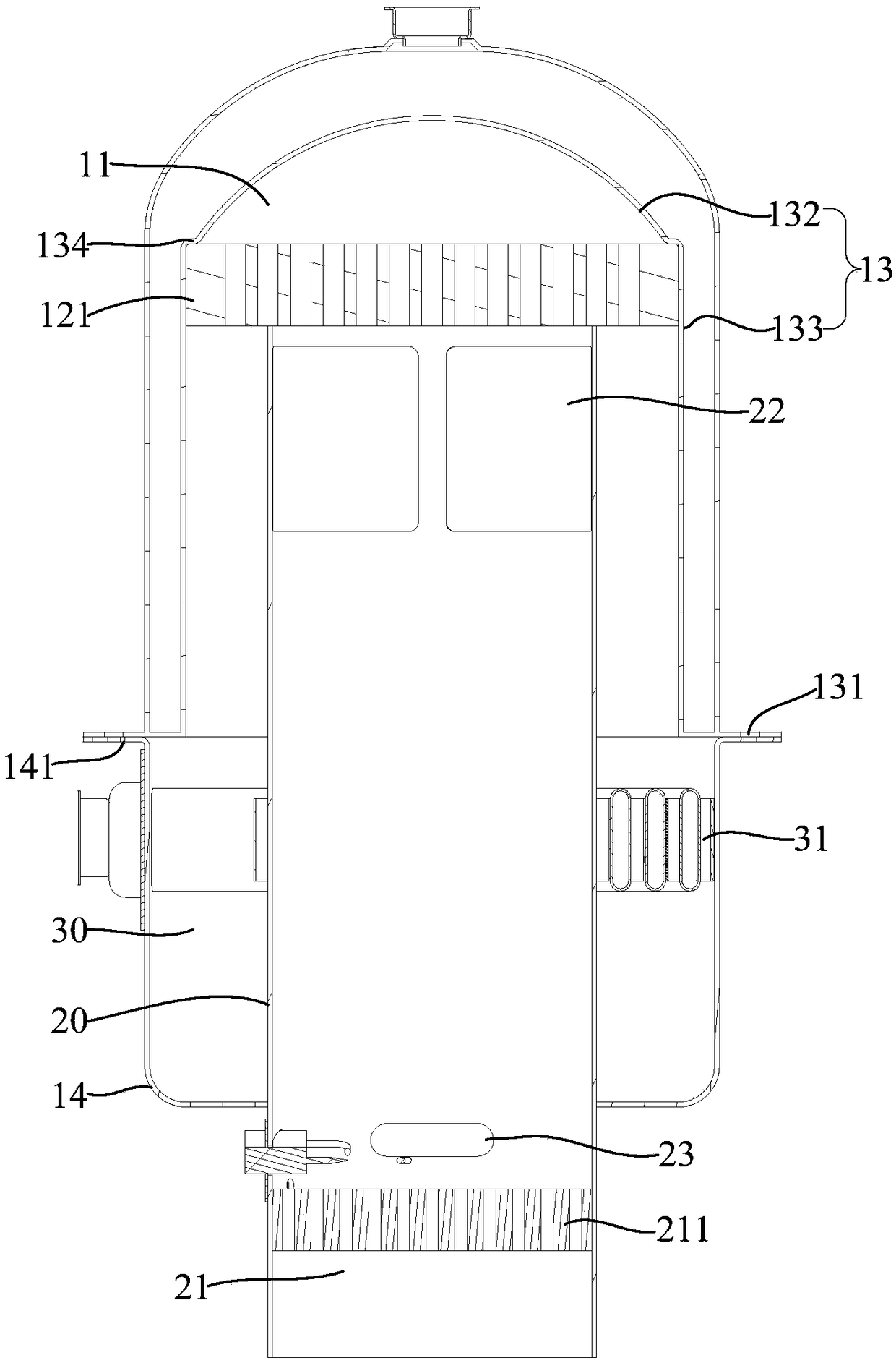
  • Combustion chamber structure and gas water heater
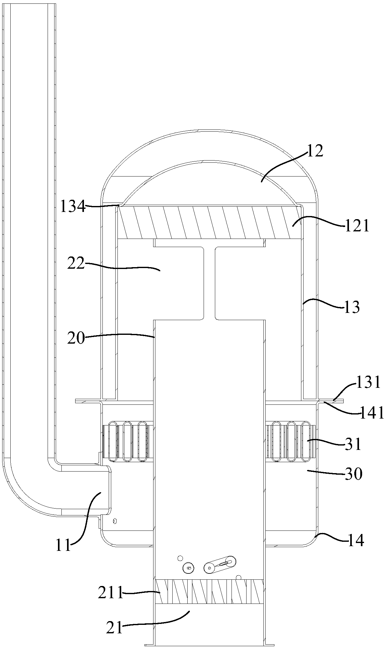
  • Combustion chamber structure and gas water heater

Examples


Embodiment Construction

[0024] The following will clearly and completely describe the technical solutions in the embodiments of the present invention with reference to the accompanying drawings in the embodiments of the present invention. Obviously, the described embodiments are only part of the embodiments of the present invention, not all of them. Based on the embodiments of the present invention, all other embodiments obtained by persons of ordinary skill in the art without creative efforts fall within the protection scope of the present invention.

[0025] It should be noted that if there is a directional indication (such as up, down, left, right, front, back...) in the embodiment of the present invention, the directional indication is only used to explain the position in a certain posture (as shown in the accompanying drawing). If the specific posture changes, the directional indication will also change accordingly.

[0026] In addition, if there are descriptions involving "first", "second" and ...


PUM


Abstract

The invention discloses a combustion chamber structure and a gas water heater. The combustion chamber structure comprises a shell and a heat collecting cylinder, wherein a smoke vent is formed in thelower end of the shell, and a catalytic combustion chamber is formed in the upper end of an inner cavity of the shell; and the heat collecting cylinder penetrates into the shell from bottom to top, the upper end of the heat collecting cylinder extends upward to the catalytic combustion chamber, and the lower end of the heat collecting cylinder is exposed to the shell and enclosed to form a preheating combustion chamber. The combustion chamber structure can effectively improve the preheating efficiency of a catalytic burner.

Description

technical field [0001] The invention relates to the field of water heaters, in particular to a combustion chamber structure and a gas water heater. Background technique [0002] At present, most of the gas water heaters have only one combustion chamber. After the gas is burned on the burner installed in the combustion chamber, the heat generated is directly discharged from the smoke outlet after being exchanged by the heat exchanger located above the burner. In the existing technology, a catalytic combustion module is installed in the combustion chamber to make the gas burn more fully, so as to improve energy utilization and reduce harmful gas emissions. However, the catalytic combustion module needs to be preheated by a common preheating burner, but the gas in the prior art The water heater directly sets the preheating burner and the catalytic combustion module in the same combustion chamber, specifically, the catalytic combustion module is set between the preheating burner...

Claims


Application Information

Patent Timeline
Patent Type & Authority Applications(China)
IPC IPC(8): F24H9/18
CPCF24H9/1836
Inventor 寿利萍梁泽锋梁国荣薛承志
Owner WUHU MIDEA KITCHEN & BATH APPLIANCES MFG CO LTD
Learn More