Vehicle fuel cell cooling device and fuel cell vehicle

A technology of fuel cell vehicles and fuel cells, which is applied in the direction of battery/fuel cell control devices, fuel cells, fuel cell additives, etc., can solve the problem of no driving wind, etc., and achieve the effect of suppressing power consumption and rapid preheating

Active Publication Date: 2014-04-02
SUZUKI MOTOR CORP
View PDF6 Cites 6 Cited by
  • Summary
  • Abstract
  • Description
  • Claims
  • Application Information

AI Technical Summary

Problems solved by technology

[0007] However, in the technique disclosed in Patent Document 1, there is a problem that there is no device for adjusting the traveling wind, and the fuel cell cannot be properly cooled by the traveling wind according to the situation.

Method used


Image

  • Vehicle fuel cell cooling device and fuel cell vehicle
  • Vehicle fuel cell cooling device and fuel cell vehicle
  • Vehicle fuel cell cooling device and fuel cell vehicle

Examples


Embodiment Construction

[0041] One embodiment of the present invention will be described below.

[0042] The fuel cell vehicle of the present embodiment is equipped with: an electric motor for driving the vehicle; and a fuel cell for supplying electric power to the electric motor.

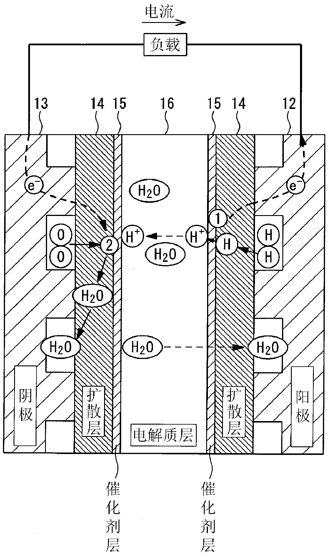
[0043] figure 1 is to describe the fuel cell vehicle 1 mounted on it (refer to Figure 2 ~ Figure 4 ) is an explanatory diagram of the structure and operation of the fuel cell. First, the electrochemical reaction of the hydrogen fuel cell 11 and the generation of water accompanying the electrochemical reaction will be described. The hydrogen fuel cell 11 is a stack formed by stacking a plurality of minimum structural units called cells. figure 1 The illustrated configuration also shows a single cell. In a common solid polymer fuel cell, each unit cell has: a diffusion layer 14 sandwiched by an anode 12 and a cathode 13 that respectively supply hydrogen and air (oxygen); and an electrolyte membrane 16 sandwiched by th...


PUM


Abstract

In the invention, a grill shutter (36) is disposed between a front grill (31) and an air intake duct (32). This grill shutter (36) can open and close a shutter member (37), and when opening the shutter member (37) the grill shutter (36) can adjust the opening degree of the shutter member (37). When the maximum air flow rate supplied by running wind is greater than the air flow rate required by a hydrogen fuel cell (11), the air flow rate required by the hydrogen fuel cell (11) is accounted for solely by means of opening-and-closing control of the shutter member (37) through the issuing of grill shutter opening degree instructions. Otherwise, the grill shutter member (37) is fully opened through the issuing of grill shutter opening degree instructions, maximizing the running wind taken in from the front grill (31), and the lacking air flow rate required by the hydrogen fuel cell (11) is accounted for by activating a blower (22) through the issuing of blower speed instructions.

Description

technical field [0001] The present invention relates to a fuel cell cooling device for a vehicle equipped with a fuel cell and a fuel cell vehicle. Background technique [0002] Patent Document 1 discloses a vehicle equipped with an air-cooled fuel cell. In this technology, the fuel cell is cooled by the running wind of the vehicle. In addition, another pressure source such as a ventilator is prepared for cooling the fuel cell. Furthermore, the vehicle speed is detected, and when the vehicle speed is low, the ventilator operates to cool the fuel cell. In addition, even when the external temperature is high, the fan is operated to cool the fuel cell. [0003] prior art literature [0004] patent documents [0005] Patent Document 1: Special Form 2000-514745 Contents of the invention [0006] The problem to be solved by the invention [0007] However, in the technique disclosed in Patent Document 1, there is a problem that there is no means for adjusting the trav...

Claims


Application Information

Patent Timeline
Patent Type & Authority Applications(China)
IPC IPC(8): B60K11/06B60K8/00B60L11/18H01M8/04
CPCY02T90/34Y02T90/32H01M8/04B60L11/1883B60L1/003B60K8/00H01M8/04701B60L11/18H01M8/0432B60L11/1898H01M2250/20B60L11/1881B60K2001/005B60L11/1892H01M8/04776Y02E60/50B60K1/00H01M8/04014B60L11/1896B60K11/06B60L58/30B60L50/72B60L58/33B60L50/71B60L50/70Y02T90/40
Inventor 橘俊英太田彻池谷谦吾松本善全大冢龙司高井善文村上贵纪
Owner SUZUKI MOTOR CORP
Why Eureka
Try Eureka