Electrostatic protection circuit

An electrostatic protection and circuit technology, applied in the direction of circuits, electrical components, electric solid devices, etc., can solve the problems that high-speed applications have a great influence, and achieve the effect of low parasitic capacitance and good electrostatic protection function

Inactive Publication Date: 2019-03-05
HIMAX TECH LTD
View PDF10 Cites 1 Cited by
  • Summary
  • Abstract
  • Description
  • Claims
  • Application Information

AI Technical Summary

Problems solved by technology

Therefore, the traditional ESD protection circuit 100 can only make the current flow from the P+ diffusion region 126 to the N+ diffusion region 124, that is, there is only one path, so if the traditional ESD protection circuit 100 wants to obtain a better ESD protection function, it must wait Increase the overall area of ​​the N-type diode 120 proportionally, but after the area increases, the parasitic capacitance will increase accordingly, which has a great impact on high-speed applications
Similarly, the P-type diode 110 also has a similar structure to the N-type diode 120, so it will cause the same problem

Method used


Image

  • Electrostatic protection circuit
  • Electrostatic protection circuit
  • Electrostatic protection circuit

Examples


Embodiment Construction

[0041] Certain terms are used in this specification and claims to refer to specific components, but those skilled in the art should understand that hardware manufacturers may use different terms to refer to the same component, and this specification and claims do not The difference in the name is used as the way to distinguish the components, but the difference in the function of the components is used as the criterion for the distinction. The "comprising" mentioned in the entire specification and claims is an open term, so It should be interpreted as "including but not limited to". In addition, the term "coupling" here includes any direct and indirect electrical connection means. Therefore, if the text describes a first device coupled to a second device , which means that the first device can be directly electrically connected to the second device, or indirectly electrically connected to the second device through other devices or connection means.

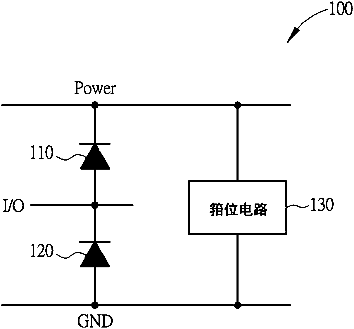
[0042] Please refer to Fig...


PUM


Abstract

The invention discloses an electrostatic protection circuit. The electrostatic protection circuit comprises a P-type diode, an N-type diode and a clamping circuit. The P-type diode comprises a P-typesemiconductor substrate, an N-well, a first N+ diffusion region, a P+ diffusion region, and a second N+ diffusion region, wherein the first N+ diffusion region is arranged in the N well; the P+ diffusion region is arranged on the periphery of the first N+ diffusion region; and the second N+ diffusion region is arranged on the periphery of the P+ diffusion region. The N-type diode comprises a P-type semiconductor substrate, a first P+ diffusion region which is arranged in the P-type semiconductor substrate of the N-type diode, an N+ diffusion region which is arranged on the periphery of the first P+ diffusion region, and a second P+ diffusion region which is arranged on the periphery of the N+ diffusion region.

Description

technical field [0001] The invention relates to an electrostatic protection circuit, in particular to an electrostatic protection circuit with an innovative diode structure, which can have better electrostatic protection function and relatively low parasitic capacitance without increasing the area. Background technique [0002] figure 1 Shown is a simplified schematic diagram of a conventional electrostatic protection circuit 100, figure 2 shown as figure 1 A top view and a schematic cross-sectional view of an N-type diode in an electrostatic protection circuit 100 of FIG. Such as figure 1 As shown, the electrostatic protection circuit 100 includes: a P-type diode 110 coupled to a power supply terminal Power and an output-output terminal I / O; an N-type diode 120 coupled to a ground terminal GND and an output-output terminal I / O; and a clamping circuit 130 connected in parallel with the P-type diode 110 and the N-type diode 120 . Such as figure 2 As shown, the N-type ...

Claims


Application Information

Patent Timeline
Patent Type & Authority Applications(China)
IPC IPC(8): H01L27/02
CPCH01L27/0255H01L27/0296
Inventor 陈鸿毅蔡青霖陈俞均郑嘉士周北翔陈明扬
Owner HIMAX TECH LTD
Why Eureka
Try Eureka