Electric connector for circuit board

A circuit substrate and electrical connector technology, applied in the direction of connection, circuit, and parts of the connection device, etc., can solve the problems of noise leakage, terminal influence, socket connector does not have, etc., and achieve a reliable locking state and strong locking strength , the effect of preventing crosstalk

Active Publication Date: 2019-03-05
HIROSE ELECTRIC GROUP
View PDF11 Cites 3 Cited by
  • Summary
  • Abstract
  • Description
  • Claims
  • Application Information

AI Technical Summary

Problems solved by technology

[0008] In addition, since the receptacle connector of Patent Document 1 does not have a metal shell member, there is no metal member on the outer side of each terminal row in the width direction of the connector (the side opposite to the side where the locking member is present).
As a result, in the above-mentioned receptacle connector, even if the crosstalk between the two terminal rows can be prevented, in each terminal row, the noise radiated from the terminals is likely to leak out of the connector, and cause the terminals to be easily affected by noise from the connection. Influence of external noise
In other words, there is concern that the above-mentioned receptacle connector and electronic equipment adjacent to it will have a negative impact on each other.

Method used


Image

  • Electric connector for circuit board
  • Electric connector for circuit board
  • Electric connector for circuit board

Examples


Embodiment Construction

[0026] Embodiments of the present invention will be described below based on the drawings.

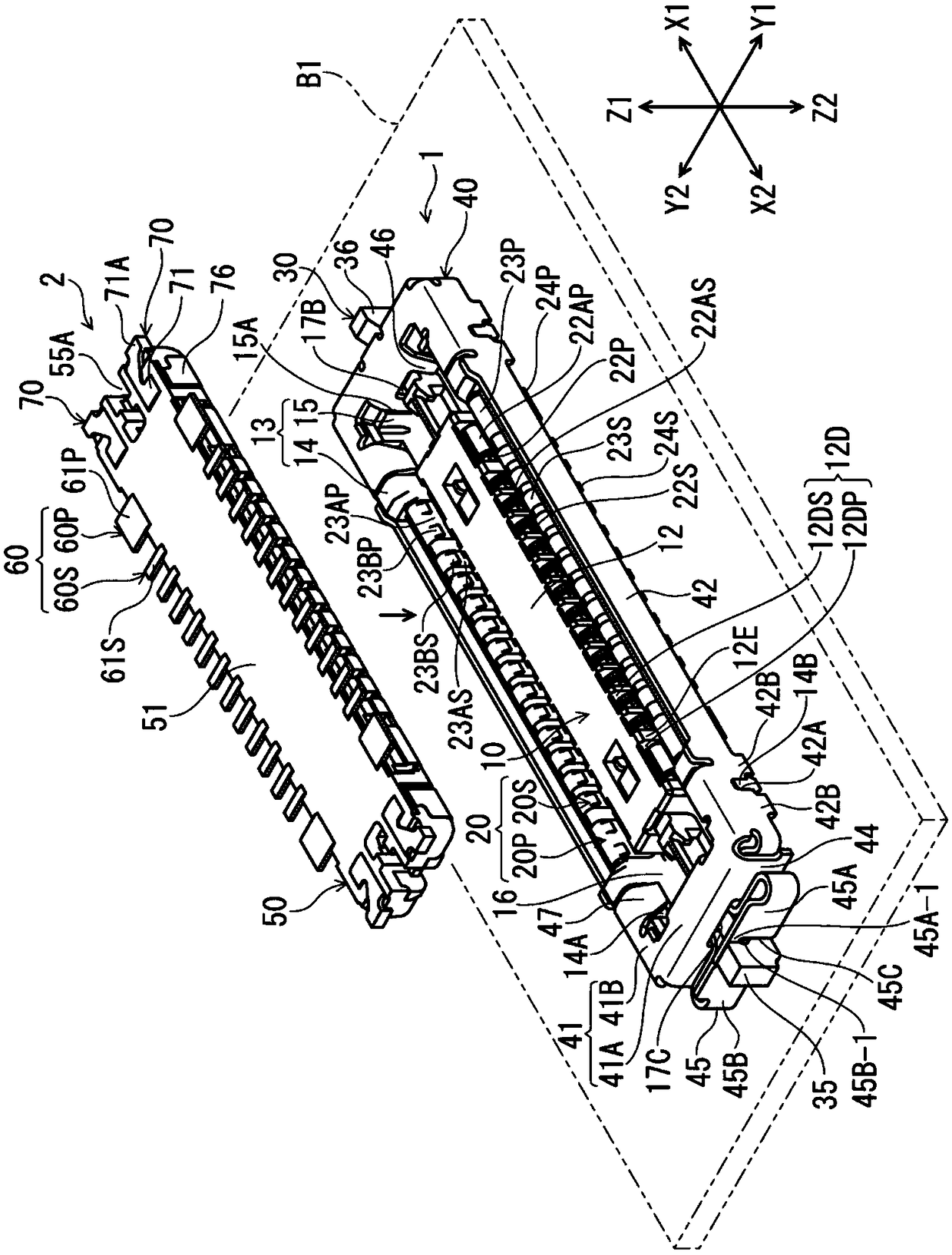
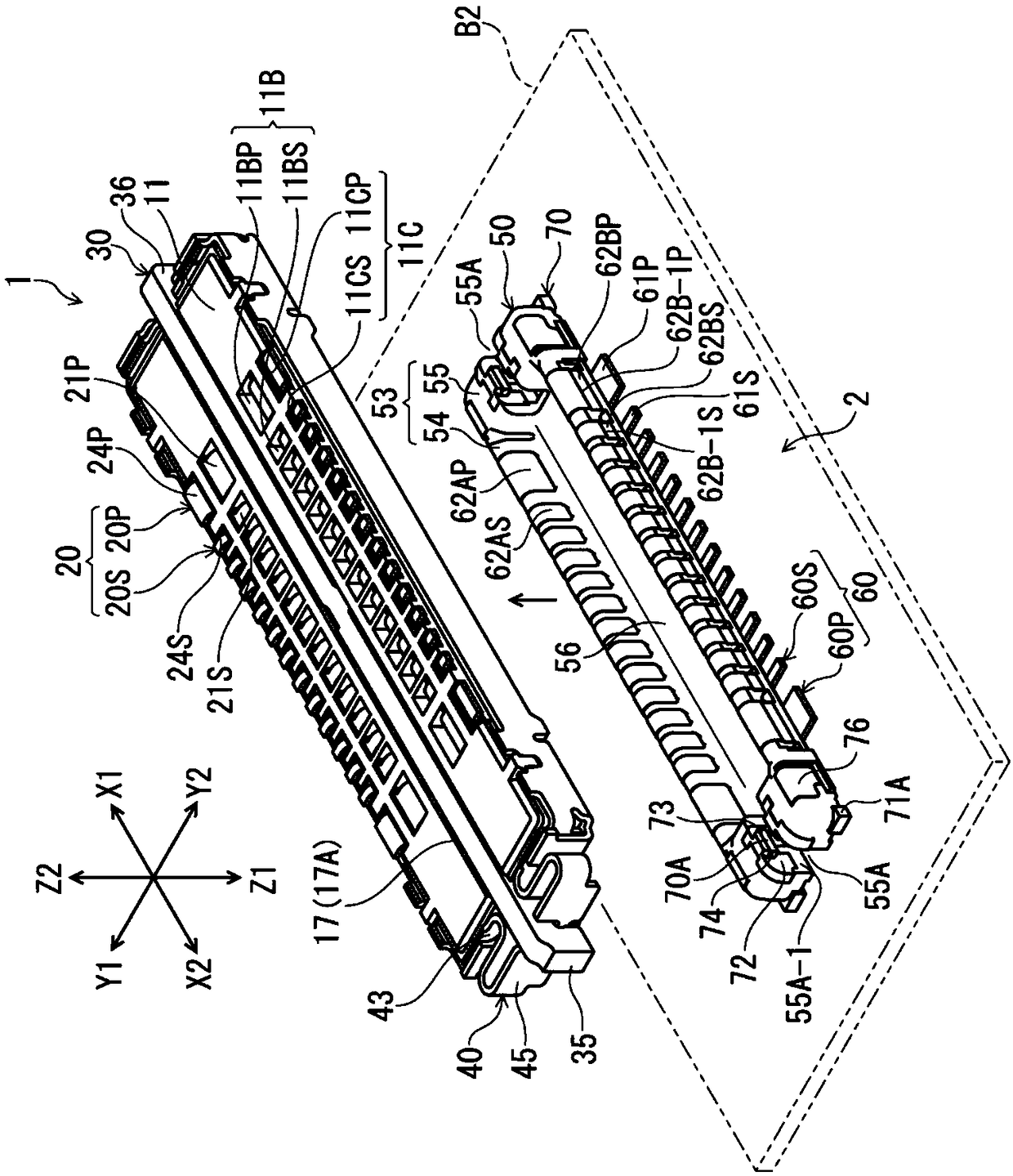
[0027] figure 1 It is a perspective view of the receptacle connector 1 of this embodiment and the plug connector 2 fitted to it from above, and shows the state before connector fitting. figure 2 is to make figure 1 It is a perspective view showing the receptacle connector 1 and the plug connector 2 turned upside down, and is a perspective view showing a posture in which the plug connector 2 is fitted from below.

[0028] The receptacle connector 1 of the present embodiment and the plug connector 2 as a target connector of the receptacle connector 1 are disposed on different circuit boards B1, B2 ( figure 1 , figure 2 The electrical connectors for circuit boards on the mounting surface shown by double-dashed lines in ) are configured in a direction at right angles to the surface of each circuit board B1, B2 ( figure 1 The up and down direction (Z-axis direction)) is used as the co...


PUM


Abstract

The invention provides an electric connector for a circuit board, which enables the locking state of the connectors to be more reliable, and well reduce the influence of noise between the two terminalcolumns and between the terminal column and the connector. A locking member (30) is located between the two terminal columns in a connector width direction that is in a straight angle with the terminal arrangement direction, and is located in the range of a contacting part between a terminal (20) and an object terminal (60) in a plugging direction of the connector, and extends in a range of the terminal arrangement range in the terminal arrangement direction. A housing member (40) is provided with a side plate part (42) which extends along the outer surface of a housing (10) in the range including the terminal arrangement range along the terminal arranging direction; and a connecting part (42B) which enables the circuit board to be connected to the corresponding circuit part. The lockingmember (30) and the housing member (40) are electrically conducted through a force applying part (45).

Description

technical field [0001] The present invention relates to an electrical connector for a circuit board that is arranged on a mounting surface of a circuit board and is removably fitted and connected to a counterpart connector. Background technique [0002] In such an electrical connector, it is preferable that the electrical connector and the mating connector which are fitted and connected to each other have a locking function for maintaining the fitted state of the connectors. In addition, when the electrical connector is used for high-speed signal transmission, it is required to minimize the external influence of noise radiated from the terminal of the electrical connector and the influence of noise received by the terminal from the outside. [0003] Patent Document 1 discloses a receptacle connector as a circuit board connector provided with a metal locking member (GCL member) having a locking function. In this receptacle connector, a plurality of terminals forming two term...

Claims


Application Information

Patent Timeline
Patent Type & Authority Applications(China)
IPC IPC(8): H01R12/71H01R13/627H01R13/633H01R13/6461H01R13/6581H01R13/502H01R13/11H01R13/04
CPCH01R12/716H01R13/04H01R13/11H01R13/502H01R13/6275H01R13/633H01R13/6461H01R13/6581H01R13/629H01R13/648
Inventor 绿川和弥
Owner HIROSE ELECTRIC GROUP
Why Eureka
Try Eureka