
Control Method of Maximum Torque-to-Current Ratio of Permanent Magnet Synchronous Motor Based on Parameter Self-modification

A technology of maximum torque current and permanent magnet synchronous motor, which is applied in motor control, motor generator control, electronically commutated motor control, etc. It can solve the problems of complex signal analysis process, system bandwidth influence, and poor dynamic response, etc., to achieve Simplified bandpass filter, good dynamic performance, simple algorithm effect

Active Publication Date: 2021-10-26
TIANJIN POLYTECHNIC UNIV
View PDF4 Cites 0 Cited by
  • Summary
  • Abstract
  • Description
  • Claims
  • Application Information

AI Technical Summary

Problems solved by technology

However, the algorithm of this method is complicated, and a large number of filters are used, which affects the system bandwidth, and the signal analysis process is complicated, and the dynamic response is poor.

Method used


Image

  • Control Method of Maximum Torque-to-Current Ratio of Permanent Magnet Synchronous Motor Based on Parameter Self-modification
  • Control Method of Maximum Torque-to-Current Ratio of Permanent Magnet Synchronous Motor Based on Parameter Self-modification
  • Control Method of Maximum Torque-to-Current Ratio of Permanent Magnet Synchronous Motor Based on Parameter Self-modification

Examples


Embodiment Construction

[0056] The method for controlling the maximum torque-to-current ratio of a permanent magnet synchronous motor based on parameter self-correction of the present invention will be described in detail below in conjunction with embodiments and drawings.

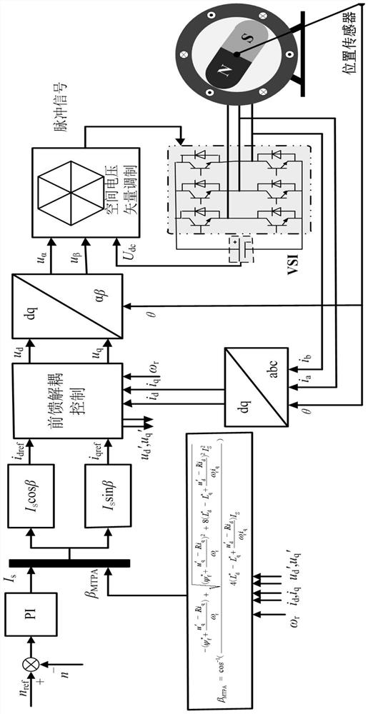
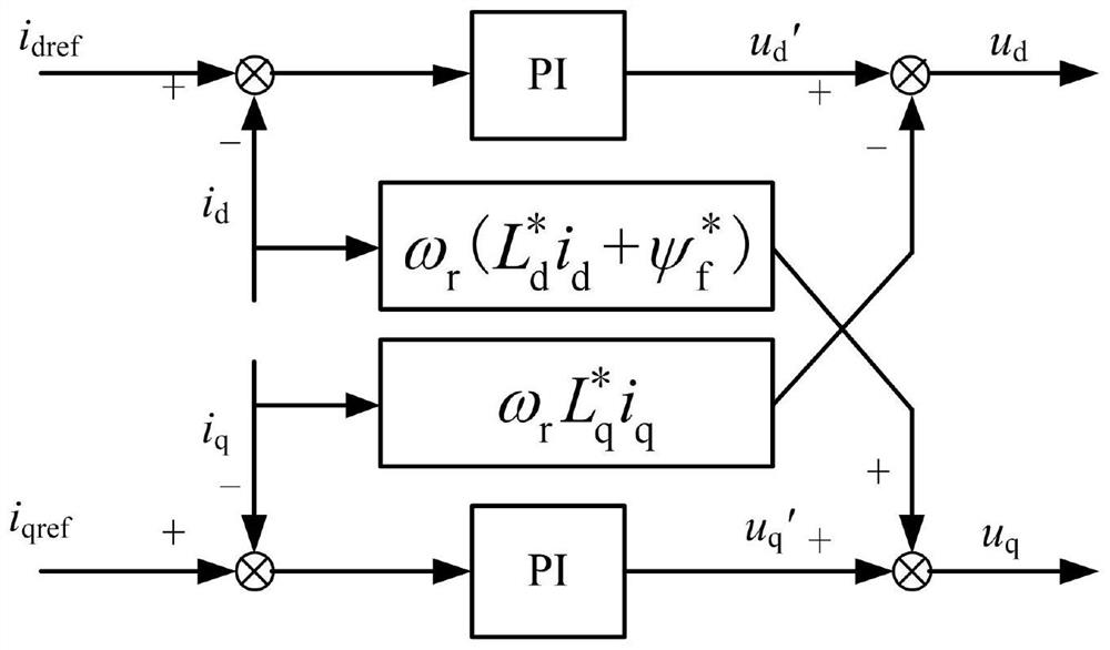
[0057] The method for controlling the maximum torque-to-current ratio of a permanent magnet synchronous motor based on parameter self-correction of the present invention corrects the changes of the motor parameters (permanent magnet flux linkage, d-axis inductance and q-axis inductance) in real time through the feedforward compensation control link, Furthermore, mathematical operations are performed on the electromagnetic torque model containing accurate motor parameter information to directly obtain the MTPA angle to replace complex signal injection and signal processing methods to solve the difficulties in the control accuracy and dynamic response speed of the existing maximum torque-to-current ratio control method. At the same ...


PUM


Abstract

A method for controlling the maximum torque-to-current ratio of permanent magnet synchronous motors based on parameter self-correction, which uses a feedforward compensation control module to estimate changes in motor parameters (permanent magnet flux linkage, d-axis inductance, and q-axis inductance) in real time, and then Correct the motor parameters in the torque equation online to obtain an electromagnetic torque model containing accurate motor parameter information, and use the model to directly calculate the torque-to-current angle change rate, and then calculate the MTPA angle to achieve accurate maximum Torque current ratio control. When the operating condition of the motor changes, the present invention uses mathematical operations to directly obtain the MTPA angle, so there is no need to consider the influence of the system bandwidth, and the algorithm is simple, the calculation speed is fast, and the dynamic performance is good, so that the motor can always run at the maximum torque current It is not affected by operating conditions and motor parameter changes, and has good parameter robustness and dynamic response characteristics.

Description

technical field [0001] The invention relates to a method for controlling the maximum torque current ratio of a permanent magnet synchronous motor. In particular, it relates to a method for controlling the maximum torque-to-current ratio of a permanent magnet synchronous motor based on parameter self-correction. Background technique [0002] The built-in permanent magnet synchronous motor has the advantages of high efficiency, high power density, simple and compact structure, and reliable operation. With the development of power electronic devices, it is widely used in electric vehicles, new energy power generation, and industrial servo drives. Because the permanent magnet of the built-in permanent magnet synchronous motor is embedded in the rotor, its q-axis inductance is significantly larger than the d-axis inductance, which causes the motor to generate reluctance torque. In order to make full use of the reluctance torque and improve the operating efficiency of the system,...

Claims


Application Information

Patent Timeline
Patent Type & Authority Patents(China)
IPC IPC(8): H02P21/00H02P21/14
CPCH02P21/00H02P21/14H02P2207/05
Inventor 王慧敏李翀元张国政史婷娜郭丽艳王志强
Owner TIANJIN POLYTECHNIC UNIV
Learn More