Charging and discharging control system and method of flywheel battery

A technology of charge and discharge control and flywheel battery, which is applied in the control system, vector control system, motor generator control, etc., can solve the problems of low power factor and low efficiency, and achieve small pulsation, fast dynamic response and stable DC voltage Effect

Inactive Publication Date: 2011-05-25
深圳飞能能源有限公司
View PDF2 Cites 18 Cited by
  • Summary
  • Abstract
  • Description
  • Claims
  • Application Information

AI Technical Summary

Problems solved by technology

[0007] One of the technical problems to be solved by the present invention is to provide a flywheel battery charge and discharge control system, which overcomes the defects of low power factor and low efficiency of the existing flywheel battery charge and discharge control system, improves system reliability, and reduces system hardware costs

Method used


Image

  • Charging and discharging control system and method of flywheel battery
  • Charging and discharging control system and method of flywheel battery
  • Charging and discharging control system and method of flywheel battery

Examples


Embodiment Construction

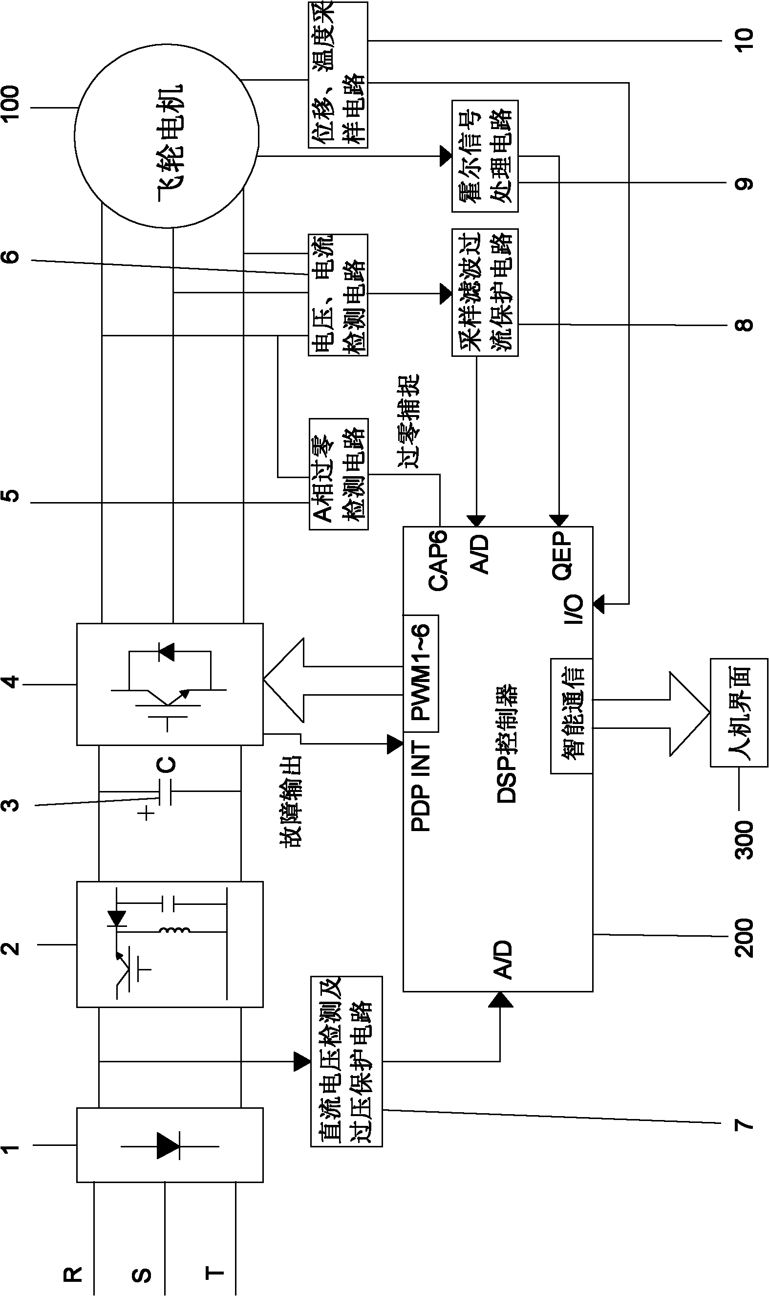
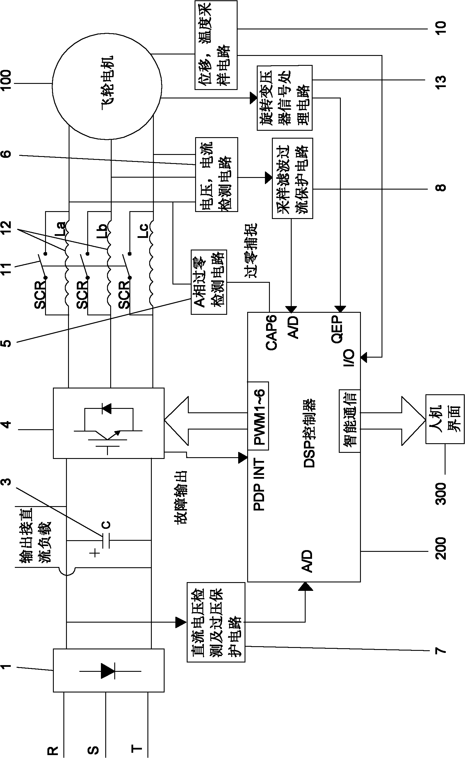
[0100] Such as figure 2 As shown, the flywheel battery charge and discharge control system of the present invention includes a three-phase uncontrolled rectifier circuit 1, an energy storage filter capacitor 3, an IGBT power conversion circuit 4, a zero-crossing detection circuit 5, a voltage and current detection circuit 6, a DC voltage detection and Overvoltage protection circuit 7, sampling and filtering overcurrent protection circuit 8, displacement and temperature sampling circuit 10, DSP controller 200, energy storage inductor 12, three-phase linkage switch 11 and resolver signal processing circuit 13.

[0101] Three-phase uncontrollable rectifier circuit 1 DC side is connected to IGBT power conversion circuit 4 DC side, IGBT power conversion circuit 4 AC side is connected to flywheel motor 100, energy storage filter capacitor 3 is connected to three-phase uncontrollable rectifier circuit 1 and IGBT power conversion circuit 4 between the DC bus.

[0102] The DC voltage detec...


PUM


Abstract

The invention discloses a charging and discharging control system and a charging and discharging control method of a flywheel battery. The system comprises a three-phase uncontrollable rectifying circuit, an energy storage filter capacitor, an insulated gate bipolar translator (IGBT) power conversion circuit, a zero passage detection circuit, a voltage detection circuit, a current detection circuit, a direct current voltage detection and overvoltage protection circuit, a sampling and filtering overcurrent protection circuit, a displacement sampling circuit, a temperature sampling circuit, a digital signal processor controller, an energy storage inductor, a three-phase linked switch and a rotary transformer signal processing circuit, wherein the energy storage inductor is connected between the output end of each phase on the alternating current side of the IGBT power conversion circuit and the input end of a flywheel motor; the three-phase linked switch is connected in parallel with the energy storage inductor respectively; and the rotary transformer signal processing circuit is connected between the signal output end of a rotary transformer of the flywheel motor and the quadrature encoder pulse (QEP) port of the DSP controller. In the method, charging and discharging control of a flywheel battery is realized based on the system. The system has stable output direct current voltage, small high-frequency ripple, quick dynamic response, and is particularly suitable for quick charging and quick discharging working conditions; and the power factor and efficiency of the system are improved greatly.

Description

Technical field [0001] The invention relates to a system for controlling the charging and discharging of a flywheel battery, and also relates to a method for controlling the flywheel battery by using the system. Background technique [0002] The charging and discharging process of flywheel battery is the basic control process of flywheel battery. At present, flywheel battery charge and discharge control systems at home and abroad use such figure 1 The AC-DC-AC system shown includes a three-phase uncontrollable rectifier circuit 1, a buck-boost chopper control circuit 2, an energy storage filter capacitor 3, an IGBT power conversion circuit 4, a zero-crossing detection circuit 5, voltage, Current detection circuit 6, DC voltage detection and overvoltage protection circuit 7, sampling filtering and overcurrent protection circuit 8, Hall signal processing circuit 9, displacement, temperature sampling circuit 10 and DSP controller 200, among which, three-phase uncontrollable rectifie...

Claims


Application Information

Patent Timeline
Patent Type & Authority Applications(China)
IPC IPC(8): H02P23/00H02P21/14H02P21/00
Inventor 党彦波刘在献李方边敬平
Owner 深圳飞能能源有限公司
Why Eureka
Try Eureka