Interlacing power-factor correction circuit and control method thereof

A technology of power factor correction and control method, applied in output power conversion devices, electrical components, high-efficiency power electronic conversion, etc., can solve problems such as different current values ​​of booster branches, potential safety hazards, damage to components, etc.

Active Publication Date: 2015-08-26
GD MIDEA HEATING & VENTILATING EQUIP CO LTD +1
View PDF3 Cites 8 Cited by
  • Summary
  • Abstract
  • Description
  • Claims
  • Application Information

AI Technical Summary

Problems solved by technology

[0004] However, due to the differences in the technology of actual components and circuits, the impedance characteristics of each step-up branch are not the same, resulting in different current values ​​for each step-up branch. Partial heating is uneven, and even when the unbalanced current e

Method used


Image

  • Interlacing power-factor correction circuit and control method thereof
  • Interlacing power-factor correction circuit and control method thereof
  • Interlacing power-factor correction circuit and control method thereof

Examples


Embodiment Construction

[0031] The following describes in detail the embodiments of the present invention, examples of which are illustrated in the accompanying drawings, wherein the same or similar reference numerals refer to the same or similar elements or elements having the same or similar functions throughout. The embodiments described below with reference to the accompanying drawings are exemplary, and are intended to explain the present invention and should not be construed as limiting the present invention.

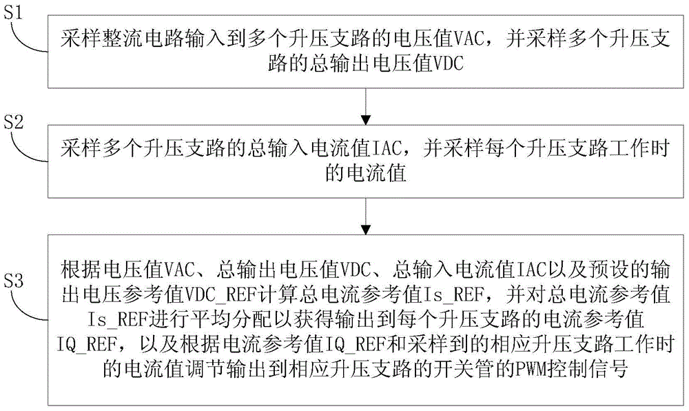
[0032] The following describes the control method of the interleaved power factor correction circuit and the interleaved power factor correction circuit according to the embodiments of the present invention with reference to the accompanying drawings.

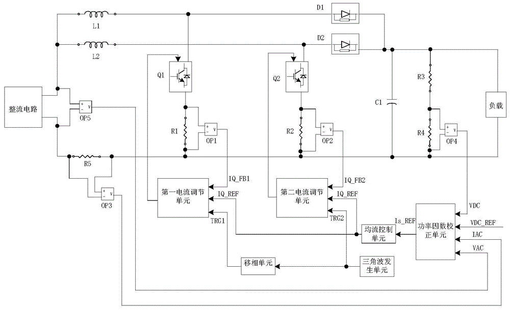
[0033] Before describing the control method of the interleaved power factor correction circuit, the interleaved power factor correction circuit will be explained first.

[0034] The interleaved power factor correction circuit includes a p...


PUM


Abstract

The invention discloses a control method of an interlacing power-factor correction circuit, and an interlacing power-factor correction circuit with the control method. The control method comprises the following step: sampling voltage values which are input to a plurality of boost branches by a rectifying circuit, sampling a total output voltage value of the plurality of boost branches; sampling a total input current value of the plurality of boost branches, sampling a current value of each boost branch in operation; according to the voltage values, the total output voltage value, the total input current value, and a preset output voltage reference value, calculating a total current reference value, and distributing the total current reference value equally to obtain a current reference value output to each boost branch, and according to the current reference values and the sampled current value of corresponding boost branches in operation, adjusting PWM control signals output to a switch tube of a corresponding boost branch. The control method effectively solves a problem of unbalance current of the interlacing power-factor correction circuit, and reliability of the circuit is improved.

Description

technical field [0001] The invention relates to the technical field of power factor correction circuits, in particular to a control method of an interleaved power factor correction circuit and an interleaved power factor correction circuit. Background technique [0002] As the country's requirements for energy utilization and efficiency of electrical equipment are getting higher and higher, the interleaved power factor correction circuit based on multiple Boost circuits in parallel is widely used in variable frequency drives due to its high efficiency, simplicity and the ability to increase the output voltage. in the device. [0003] At present, the interleaved power factor correction circuit generally adopts the control scheme of outputting a symmetrical duty cycle, that is, the power factor correction module calculates the current reference value of the boost circuit, and generates a PWM control signal with a specified duty cycle. Output to the boost branch power tube, mu...

Claims


Application Information

Patent Timeline
IPC IPC(8): H02M1/42
CPCH02M1/4225Y02B70/10
Inventor 张晓东
Owner GD MIDEA HEATING & VENTILATING EQUIP CO LTD
Why Eureka
Try Eureka